
Thermoelectric apparatus and articles and applications thereof

a technology of thermoelectric apparatus and articles, applied in the field of thermoelectric materials, can solve the problems of significant heat energy escape into the environment, 15 terawatts of power loss to the environment, and low efficiency of current thermoelectric energy conversion, etc., and achieve the effect of overcoming or reducing one or more disadvantages of current thermoelectric materials

Active Publication Date: 2016-02-04
WAKE FOREST UNIV
View PDF3 Cites 29 Cited by
  • Summary
  • Abstract
  • Description
  • Claims
  • Application Information

AI Technical Summary

Benefits of technology

This patent describes a new type of thermoelectric material that can overcome certain drawbacks of current materials. The material consists of layers of n-doped carbon nanoparticles and p-type carbon nanoparticles with an insulating layer in between. The nanoparticles can be mixed into polymers or particles that show piezoelectric behavior. The material can efficiently convert thermal energy into electrical energy, even on difficult surfaces. It can also be used in clothing, covering electronic devices, or even on the skin of humans. This new material solves certain problems with current thermoelectric materials and expands the potential applications for this technology.

Problems solved by technology

However, the efficiency of converting heat energy into electrical energy by current methods is low, ranging from about 30 to 40 percent.
As a result, a significant amount of heat energy escapes into the environment as waste.
It is estimated that about 15 terawatts of power is lost to the environment in the annual global production of electricity.
Fabricating thermoelectric materials with reasonable ZT values is often difficult and / or expensive.
These materials can be nanostructured to produce a superlattice structure of alternating Bi2Te3 and Bi2Se3 layers resulting in a material having acceptable electrical conductivity and poor thermal conductivity.
Fabrication of these materials, nevertheless, can be time consuming and expensive.
Moreover, as a result of fabrication requirements and other material tolerances, many thermoelectric materials do not lend themselves to facile incorporation into a wide variety of devices for heat collection and electrical generation.

Method used


Image

  • Thermoelectric apparatus and articles and applications thereof
  • Thermoelectric apparatus and articles and applications thereof
  • Thermoelectric apparatus and articles and applications thereof

Examples


example 1

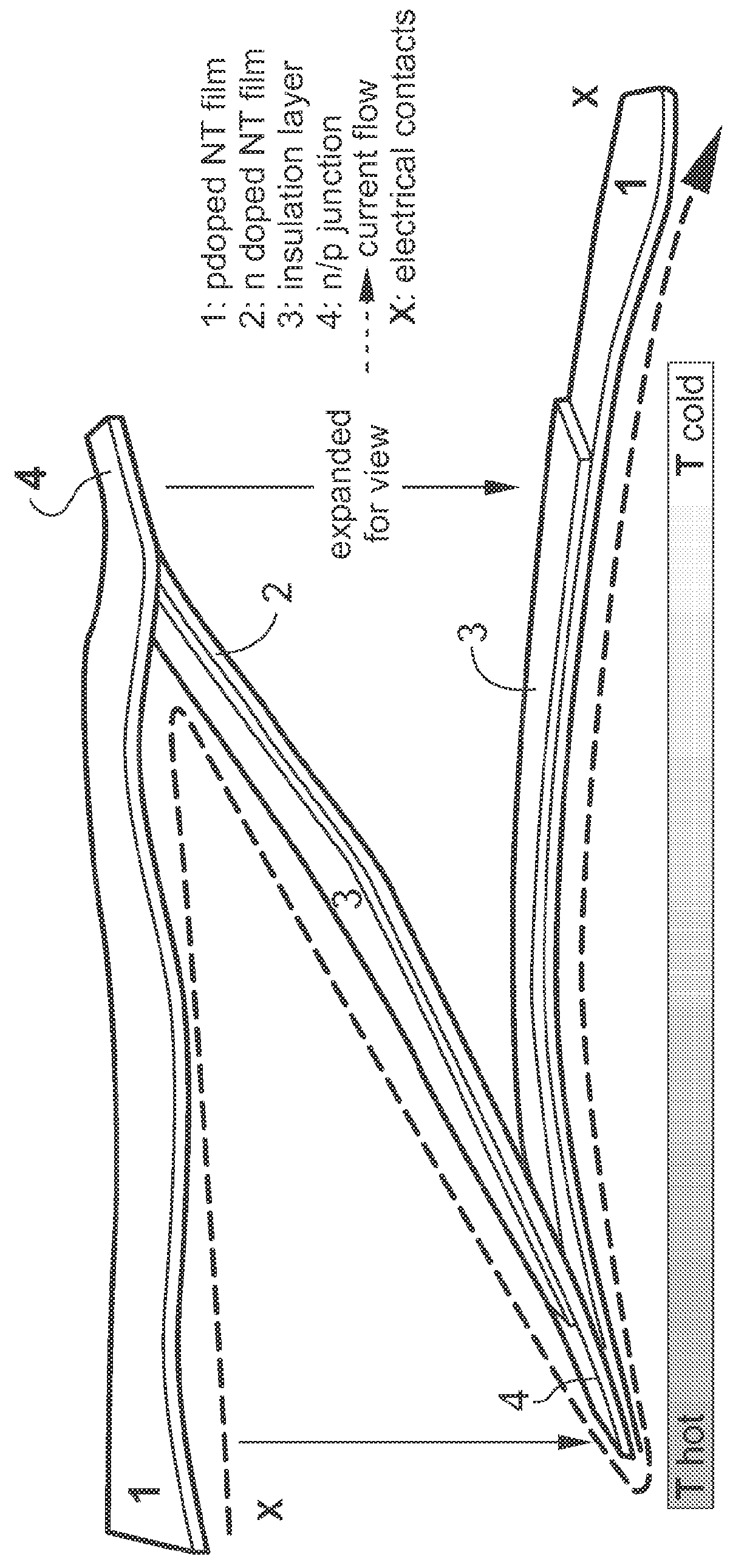
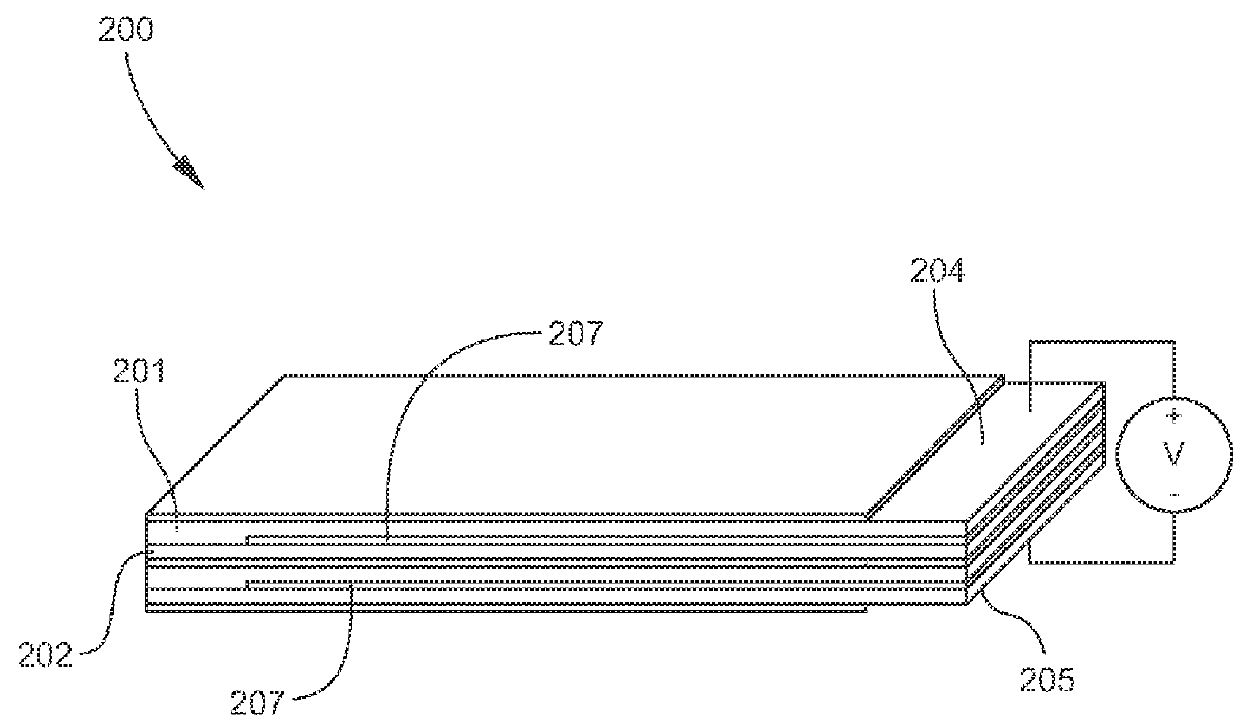
Thermoelectric Apparatus

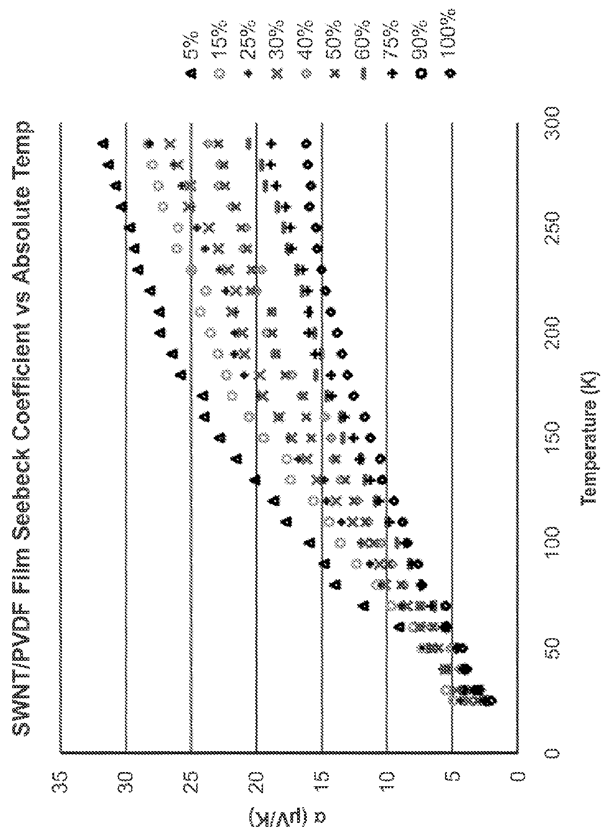
[0225]A first p-type layer was fabricated by providing 35 mg of single-walled carbon nanotubes (SWNT) to which was added 17.5 ml of dimethylacrylamide (DMA). The resulting mixture was high energy sonicated for a period of one hour. Polyvinylidene fluoride (PVDF) was added to the mixture in an amount to render the SWNT 20 weight percent of the mixture on a total solids basis. The resulting SWNT / PVDF / DMA mixture was high energy sonicated for one hour.

[0226]A glass slide having dimensions of 75 mm×45 mm was cleaned in methanol and placed on a hot plate at 90° C. The SWNT / PVDF / DMA mixture was poured evenly onto the slide and the DMA was allowed to evaporate. The dried SWNT / PVDF film was placed into an oven at 100° C. for 12 hours to anneal. The slide was subsequently removed from the oven and methanol was poured over the SWNT / PVDF film. The SWNT / PVDF film was carefully removed from the glass slide, washed in deionized water and dried.

[0227]A second p-type layer w...


PUM

PropertyMeasurementUnit
Percent by massaaaaaaaaaa

Abstract

In one aspect, thermoelectric apparatus and articles and various applications of thermoelectric apparatus and articles are described herein. In some embodiments, a thermoelectric apparatus described herein comprises at least one p-type layer coupled to at least one n-type layer to provide a pn junction, and an insulating layer at least partially disposed between the p-type layer and the n-type layer, the p-type layer comprising carbon nanoparticles and the n-type layer comprising n-doped carbon nanoparticles. In some embodiments, the nanoparticles of the p-type layer and / or the nanoparticles of the n-type layer are disposed in a polymeric matrix comprising electrically poled polymer. In some embodiments, a thermoelectric article comprises a thermally insulating support and thermoelectric modules formed of a structure passing around or through the thermally insulating support to provide faces of the thermoelectric modules on opposing sides of the thermally insulating support.

Description

CROSS REFERENCE TO RELATED APPLICATIONS[0001]This application claims priority pursuant to 35 U.S.C. §119(e) to U.S. Provisional Patent Application Ser. No. 61 / 783,709, filed on Mar. 14, 2013, and to U.S. Provisional Patent Application Ser. No. 61 / 808,472, filed on Apr. 4, 2013, which are hereby incorporated by reference in their entireties.FIELD[0002]The present invention relates to thermoelectric materials and, in particular, to apparatus, articles, and fabrics incorporating thermoelectric materials.BACKGROUND OF THE INVENTION[0003]Heat energy is widely used in the generation of electricity. However, the efficiency of converting heat energy into electrical energy by current methods is low, ranging from about 30 to 40 percent. As a result, a significant amount of heat energy escapes into the environment as waste. It is estimated that about 15 terawatts of power is lost to the environment in the annual global production of electricity.[0004]Thermoelectric materials are operable to ca...

Claims


Application Information

Patent Timeline
IPC IPC(8): H01L35/32H01L35/22H01L51/00
CPCH01L35/32H01L51/004H01L35/22H10N10/855H10N10/17H10N30/30H10K85/141
Inventor CARROLL, DAVID L.SUMMERS, ROBERT
Owner WAKE FOREST UNIV
Features
  • Generate Ideas
  • Intellectual Property
  • Life Sciences
  • Materials
  • Tech Scout
  • Unparalleled Data Quality
  • Higher Quality Content
  • 60% Fewer Hallucinations
Learn More