Optical patterning mask and method of fabricating display device using the same

a technology of optical patterning and display device, which is applied in the direction of printing, layered products, and thermography, etc., can solve the problems of uneven thickness of eml formed by transferring eml material layer onto the substrate deterioration of display quality of organic light-emitting display device, and inability to meet the requirements of the optical patterning mask. achieve the effect of improving the reproducibility of the optical patterning mask

Inactive Publication Date: 2016-02-11
SAMSUNG DISPLAY CO LTD
View PDF5 Cites 7 Cited by
  • Summary
  • Abstract
  • Description
  • Claims
  • Application Information

AI Technical Summary

Benefits of technology

[0013]Exemplary embodiments of the present invention provide an optical patterning mask for forming a pattern layer with a uniform thickness and improving the reproducibility of the optical patterning mask from repeated use.
[0014]Exemplary embodiments of the present invention also provide a method of fabricating a display device using an optical patterning mask for forming a pattern layer with a uniform thickness and improving its reproducibility from repeated use.
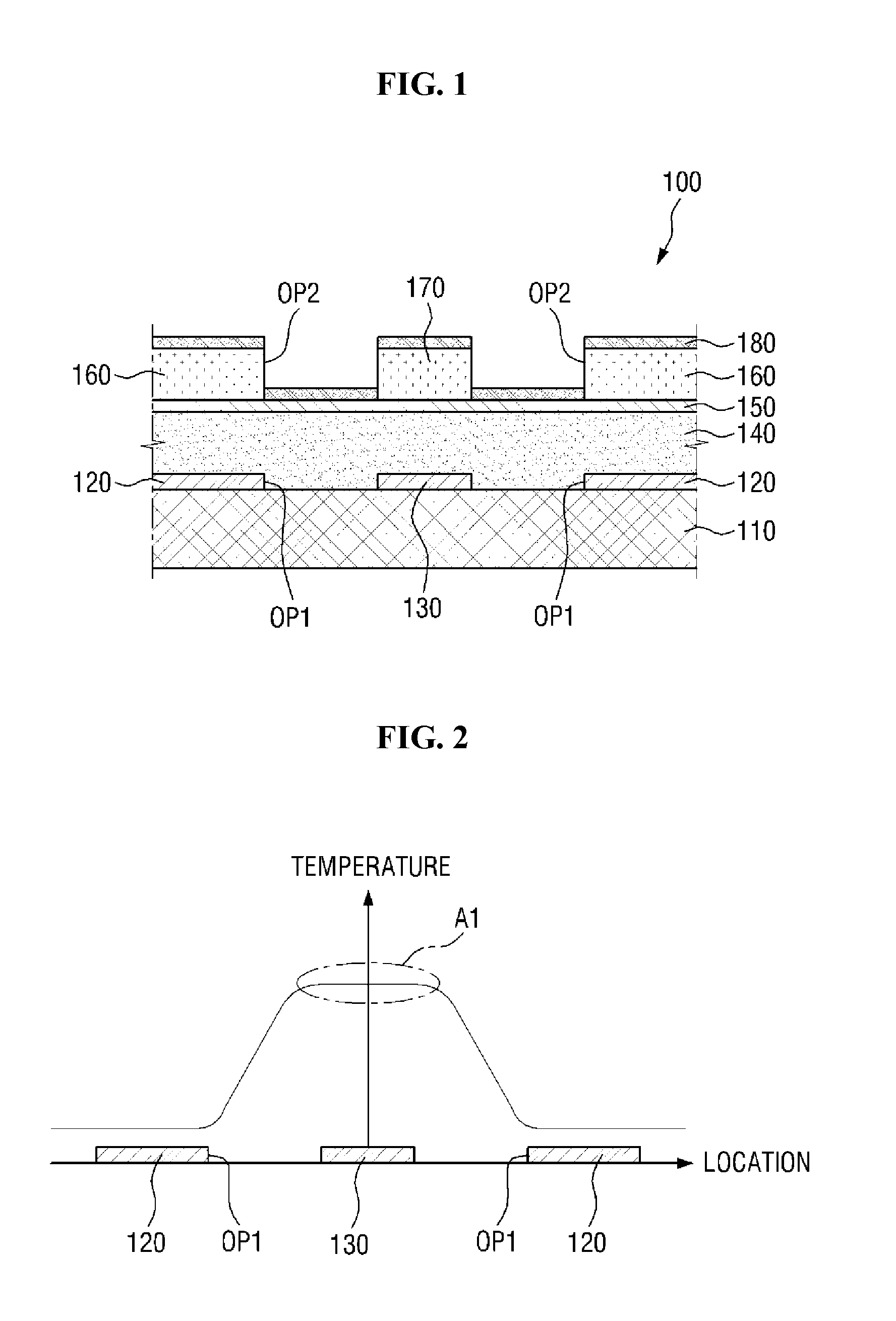
[0036]According to the exemplary embodiments, a pattern layer (for example, an EML) having a uniform thickness may be formed on a predetermined substrate (for example, the substrate of a display device) through the transfer of the transfer material of a transfer layer, and thus a display device with an improved quality of display may be produced.
[0037]In addition, the thermal conduction prevention pattern may prevent the transfer material of the transfer layer from being additionally transferred and deposited onto the predetermined substrate. Accordingly, the thickness of a pattern layer formed on the predetermined substrate through the transfer of the transfer material of the transfer layer may be uniform.
[0038]Moreover, the amount of the transfer material of the transfer layer sublimated and deposited on each predetermined substrate may be evenly maintained after repeated use of the optical patterning mask. Accordingly, the reproducibility from repeated use of the optical patterning mask may be improved.

Problems solved by technology

However, the temperature of the thermal energy output from the light-to-heat conversion layer when absorbing light may not be uniform throughout the light-to-heat conversion layer.
Thus the thickness of the EML formed by transferring the EML material layer onto the substrate of the organic light-emitting display device may become irregular.
As a result, the display quality of the organic light-emitting display device may deteriorate.
Accordingly, the reproducibility from repeated use of the donor substrate may deteriorate.

Method used


Image

  • Optical patterning mask and method of fabricating display device using the same
  • Optical patterning mask and method of fabricating display device using the same
  • Optical patterning mask and method of fabricating display device using the same

Examples


Embodiment Construction

[0050]In the following description, for the purposes of explanation, numerous specific details are set forth in order to provide a thorough understanding of various exemplary embodiments. It is apparent, however, that various exemplary embodiments may be practiced without these specific details or with one or more equivalent arrangements. In other instances, well-known structures and devices are shown in block diagram form in order to avoid unnecessarily obscuring various exemplary embodiments.

[0051]In the accompanying figures, the size and relative sizes of layers, films, panels, regions, etc., may be exaggerated for clarity and descriptive purposes. Also, like reference numerals denote like elements.

[0052]When an element or layer is referred to as being “on,”“connected to,” or “coupled to” another element or layer, it may be directly on, connected to, or coupled to the other element or layer or intervening elements or layers may be present. When, however, an element or layer is re...


PUM

PropertyMeasurementUnit
thermalaaaaaaaaaa
shapeaaaaaaaaaa
thermal insulatingaaaaaaaaaa

Abstract

An optical patterning mask, including a base substrate, a reflective layer disposed on the base substrate, the reflective layer including a first opening, a shadow pattern disposed on the base substrate and in the first opening, a thermal insulation layer disposed on the base substrate and covering the reflective layer and the shadow pattern, an absorption layer disposed on the thermal insulating layer, a bank layer disposed on the absorption layer, the bank layer including a second opening overlapping the first opening, a thermal conduction prevention pattern disposed on the absorption layer and overlapping the shadow pattern, and a transfer layer disposed on the absorption layer, the bank layer, and the thermal conduction prevention pattern.

Description

CROSS-REFERENCE TO RELATED APPLICATION[0001]This application claims priority from and the benefit of Korean Patent Application No. 10-2014-0100554, filed on Aug. 5, 2014, which is hereby incorporated by reference for all purposes as if fully set forth herein.BACKGROUND[0002]1. Field[0003]Exemplary embodiments of the present invention relate to an optical patterning mask and a method of fabricating a display device using the same.[0004]2. Discussion of the Background[0005]An organic light-emitting display device (OLED) is a self light-emitting type display device that has garnered much attention as a next-generation display device because of its wide viewing angle, excellent contrast, and fast response rate characteristics.[0006]The organic light-emitting display device may include an anode electrode, a cathode electrode, and an organic light-emitting layer (EML) provided between the anode electrode and the cathode electrode and formed of an organic light-emitting material. In respon...

Claims


Application Information

Patent Timeline
Patent Type & Authority Applications(United States)
IPC IPC(8): H01L51/00H01L27/32
CPCH01L27/3244H01L51/0013H10K71/18B41M5/48B41M5/426B41M5/42
Inventor KWON, YOUNG, GIL
Owner SAMSUNG DISPLAY CO LTD
Why Eureka
Try Eureka