
Power management concept in DC distributed systems

a distributed system and power management technology, applied in the direction of dc network load balancing, dc source parallel operation, electric variable regulation, etc., can solve the problems of high aging and tolerance of sensors, high cost and low flexibility, and difficult system stability

Inactive Publication Date: 2016-02-11
ARDA POWER
View PDF3 Cites 14 Cited by
  • Summary
  • Abstract
  • Description
  • Claims
  • Application Information

AI Technical Summary

Benefits of technology

The patent describes a system for controlling the voltage in a distributed DC power system. The system uses a main element to regulate the voltage, while other elements in the system measure the voltage and adjust their output to match the average voltage. This ensures a stable system and allows for easy calibration. The average voltage can be adjusted using different terms based on the specific needs of each element. The smooth control of the voltage and the progressive response of the elements connected to the bus enable a plug and play system where new resources and loads can be added without needing to reconfigure the main element controlling the voltage. The system is also robust against tolerances in voltage measurements. Overall, the patent describes a technical solution for efficiently controlling voltage in a distributed DC power system.

Problems solved by technology

Wired and wireless communication means are commonly used to achieve power and energy balance between the different elements at the expense of extra cost and low flexibility.
Also, aging and tolerances in sensors degrade highly the performance of the DC distributed system.In other cases, DC bus voltage changes, resulting from changes in the power balance, trigger reactions in multiple or all of the elements to balance the power and maintain the DC bus within a specified range of voltages.
In this case, the system stability is difficult to achieve and oscillations are common.
Furthermore, for these concepts it is not possible to incorporate a second function, such as energy management, on top of the power balancing.

Method used


Image

  • Power management concept in DC distributed systems
  • Power management concept in DC distributed systems

Examples


Embodiment Construction

[0022]Example of a DC Micro-grid with Variable DC-link Voltage for Energy Management

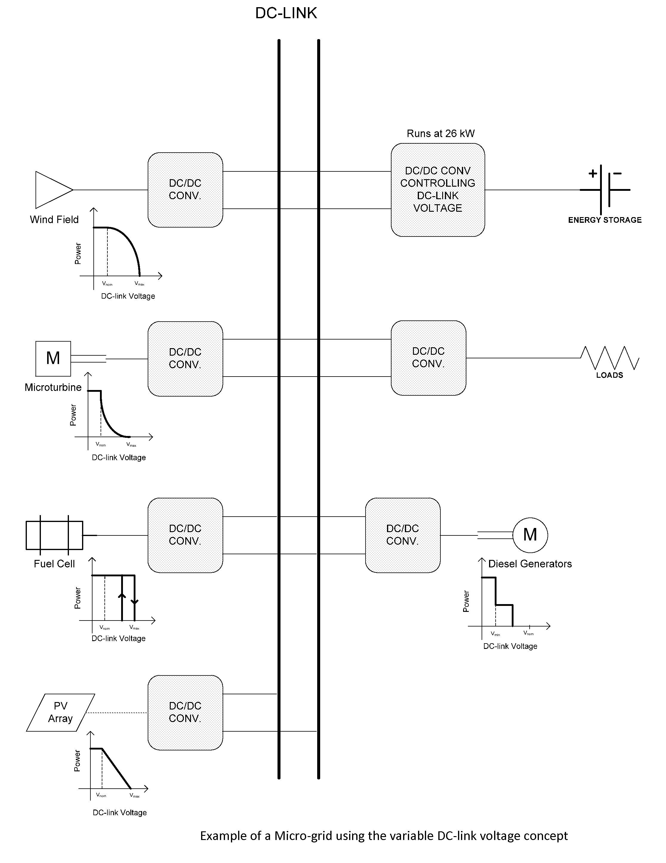
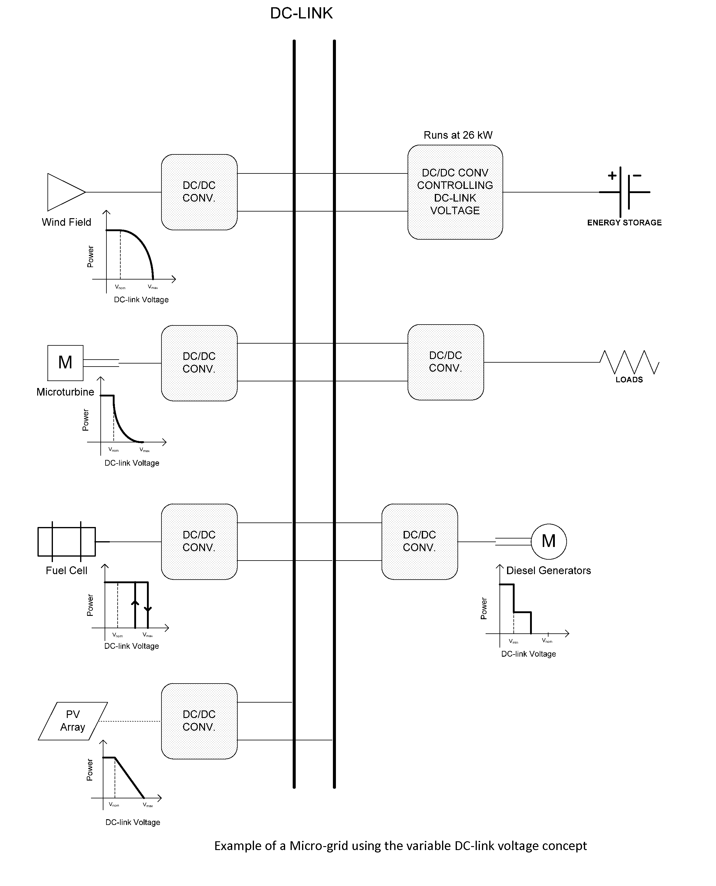
[0023]An example of the general concept of the use of variable average DC voltage for optimization of distributed sources and loads is shown in FIG. 3. Here a DC micro-grid with alternative and conventional power generators and loads in a common DC-link, operate in unison. An energy storage resource is used to instantaneously balance the generation with the load and maintaining the DC-link voltage at the desired level. A controller that may or may not be part of the energy storage unit, is responsible for keeping the state of charge for the energy storage within limits. The energy storage controller could adjust the DC-link voltage to get more or less energy from the distributed resources and the distributed resources could have different power vs average DC-link voltage (PvsV) functions depending on the cost and benefit of operating each of these distributed resources as is indicated in FIG. 3. The ...


PUM


Abstract

A system and method to interconnect several conventional or alternative power generators, loads, and / or energy storage elements physically separated from each other in a DC distribution system. The method includes the steps of providing a common DC bus to interconnect all of the elements in the DC distributed system using power converters. A first group of one or more of the elements (main element) is used to automatically maintain the voltage of the DC link following a set a set point to provide for the load matching. The average DC link voltage (set point) maintained by the main element is intentionally changed in order to indicate all of the other elements connected to the DC bus how they need to modify their power generation or consumption.

Description

CROSS-REFERENCE TO CO-PENDING APPLICATIONS[0001]This application is a continuation-in-part of U.S. patent application Ser. No. 13 / 828,290 filed Mar. 14, 2013 and claims priority on U.S. Provisional Patent Application Ser. No. 62 / 182,788, filed Jun. 22, 2015.BACKGROUND OF THE INVENTION[0002]1. Field of the Invention[0003]The present invention is a method and system to interconnect several conventional or alternative power generators, loads, and / or energy storage elements physically separated from each other in a DC distribution system.[0004]2. Prior Art[0005]Distributed DC systems are used to exchange power among multiple sources (mainly renewable energy resources), loads, and energy storage elements by connecting those elements to a common DC bus using power converters or direct connection in a concept generally called DC microgid. DC microgrids could be as simple as solar+storage installation or as complex as multi MW systems with many types of different generators, multiple rating...

Claims


Application Information

Patent Timeline
IPC IPC(8): H02J3/38H02J1/00H02M3/04
CPCH02J3/382H02J1/00H02M3/04H02J3/386H02J3/387H02J3/383G05F1/12H02J1/12H02J1/14H02J1/102H02J3/381Y02P80/14H02J2300/30H02J2300/28H02J2300/24Y02E10/56Y02E10/76
Inventor ZUBIETA, LUIS
Owner ARDA POWER
Learn More