Motor and End Cap Assembly Thereof

a technology of end cap and motor, which is applied in the direction of dynamo-electric machines, rotary current collectors, electrical apparatus, etc., can solve the problems of electrical interference with neighboring electronic equipment, and achieve the effect of suppressing

Active Publication Date: 2016-02-11
JOHNSON ELECTRIC SA
View PDF5 Cites 7 Cited by
  • Summary
  • Abstract
  • Description
  • Claims
  • Application Information

AI Technical Summary

Benefits of technology

[0020]In the present invention, high frequency electromagnetic interference signals coupled to the metal elements positioned around the m

Problems solved by technology

When the motor is in operation, current commutation and sparks are generated by the commutator segments of the commutator rotating relative

Method used


Image

  • Motor and End Cap Assembly Thereof
  • Motor and End Cap Assembly Thereof
  • Motor and End Cap Assembly Thereof

Examples


first embodiment

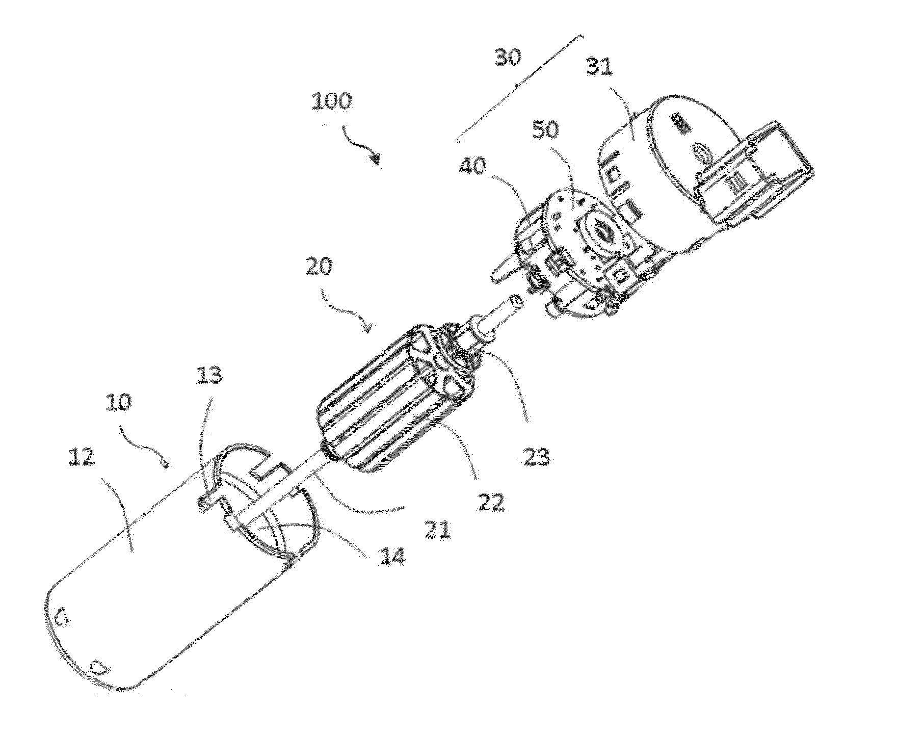
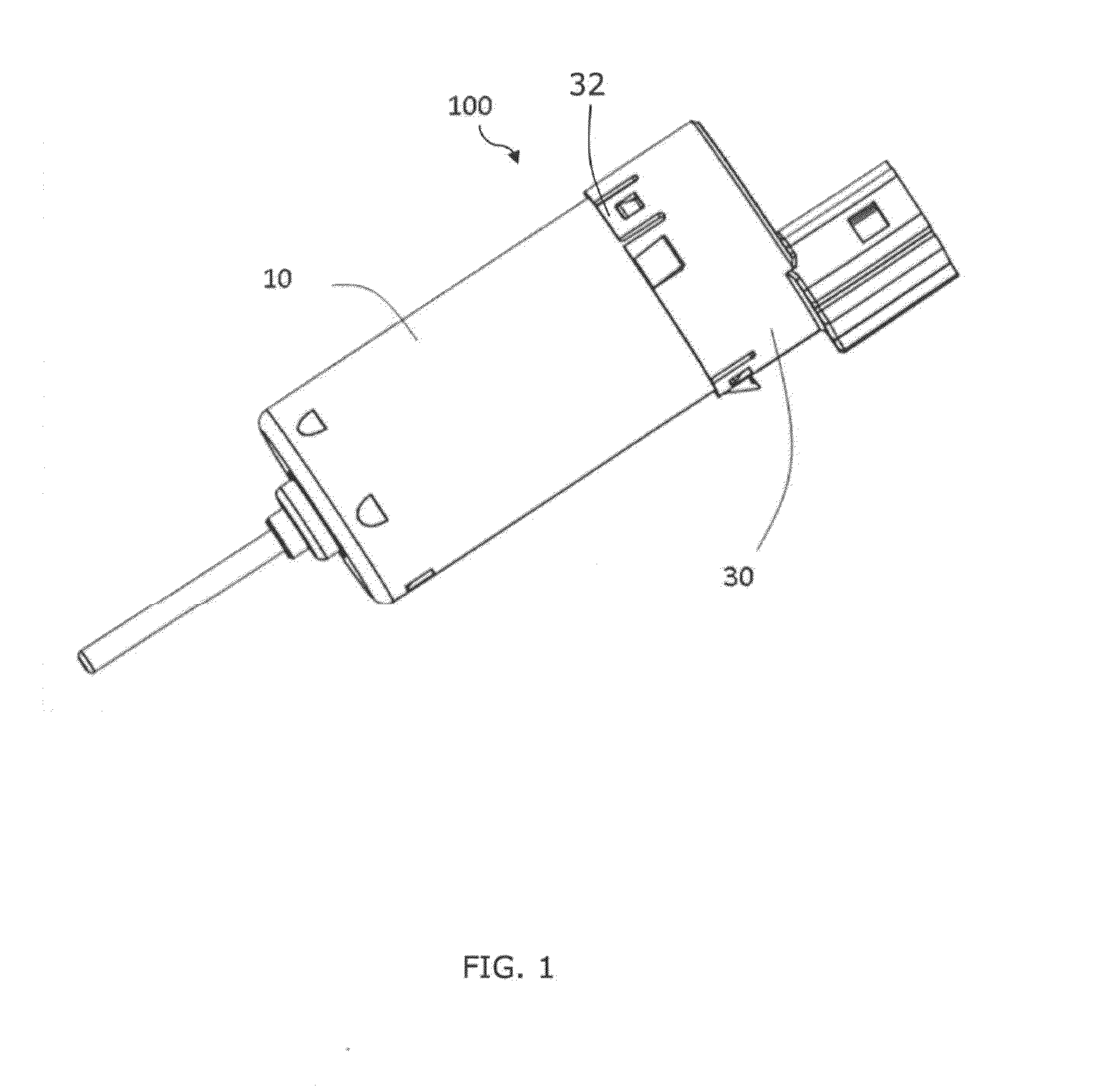
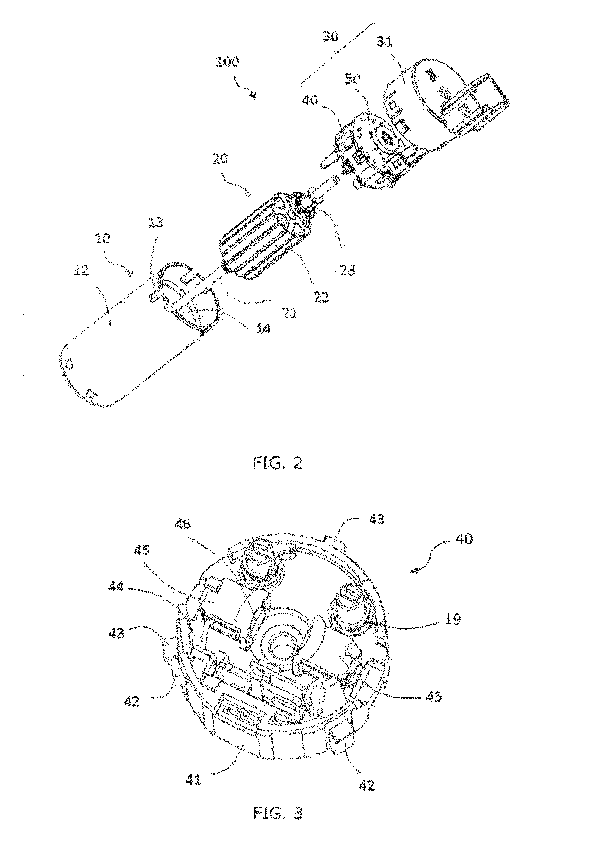
[0035]Referring to FIGS. 1 and 2, a motor 100 provided by present invention comprises a stator 10, a rotor 20 and an end cap assembly 30. The stator 10 comprises a housing 12 and a magnet 14 attached to an inner wall of the housing 12. The housing 12 has an open end. A plurality of positioning slots 13 is defined in a circumferential periphery of the open end of the housing 12.

[0036]The rotor 20 comprises a shaft 21, a rotor core 22 and a commutator 23 both fixed to the shaft 21, and a rotor winding comprising a number of coils (not shown) wound on the core 22 and electrically connected to segments of the commutator 23.

[0037]The end cap assembly 30 comprises an end cap 31, and a brush assembly 40 and a circuit board 50 both received in the end cap 31. The circuit board 50 is fixed at one side of the brush assembly 40. Latches 32 are defined in the circumferential wall of the end cap 31.

[0038]Referring to FIGS. 3, 4 and 5, the brush assembly 40 comprises an insulating bracket 41. The...

second embodiment

[0047]FIG. 9 shows a motor 80 provided by the present invention. The motor 80 comprises a stator 81, a rotor 82 (see FIG. 12) and an end cap assembly 83. The housing 84 of the stator 81 has an open end into which the end cap assembly 83 is inserted. A cover or end cap, forming a part of the end cap assembly has been omitted to show the inner parts of the end cap assembly more clearly.

[0048]Also referring to FIGS. 10, 11 and 12, the inner face of the end cap assembly 83 has two brush cages 85 each for receiving a brush 86 therein. The brushes 86 are in sliding contact with the commutator of the rotor 82. In the present embodiment, the brush cages 85 are made of a metal material. Therefore, once the high frequency electromagnetic radiation generated by the brushes 86 rotating relative to the commutator of the rotor 82 are coupled to the brush cages 85, the brush cares 85 become transmitting antennas that transmit the high frequency interference signals outwards. To avoid this situatio...


PUM


Abstract

An end cap assembly for an electric motor has a brush assembly, a circuit board, an inductor and a grounded metal element. The brush assembly has a plurality of brushes. The circuit board is fixed relative to the brush assembly. The inductor is electrically connected to the circuit board. The grounded metal element is positioned between the brushes and the inductor to absorb high frequency electromagnetic radiation transmitted from the brushes to the inductor.

Description

CROSS REFERENCE TO RELATED APPLICATIONS[0001]This non-provisional patent application claims priority under 35 U.S.C. §119(a) from Patent Application No. 201410385348.7 filed in The People's Republic of China on Aug. 6, 2014, the entire contents of which are hereby incorporated by reference.FIELD OF THE INVENTION[0002]This invention relates to electric motors and in particular, to an electric motor with an end cap assembly for suppressing electromagnetic interference (EMI).BACKGROUND OF THE INVENTION[0003]To decrease EMI by a brush motor with electronic elements arranged around the brush motor, a filter circuit is disposed between the brush and the external power source. The filter circuit includes inductors and / or capacitors. When the motor is in operation, current commutation and sparks are generated by the commutator segments of the commutator rotating relative to the brush, which results in electromagnetic radiation which may cause electromagnetic interference with neighboring el...

Claims


Application Information

Patent Timeline
IPC IPC(8): H02K11/02H02K5/14
CPCH02K5/148H02K11/026H02K23/66
Inventor LAI, CHI WAILUO, QING BINXU, GONG WUWEI, XIN PENGREN, XIAO LINTIAN, GUI HONGZHANG, HONG WEIHAN, XIA
Owner JOHNSON ELECTRIC SA
Why Eureka
Try Eureka