Time based offset correction for imaging systems

a technology of offset correction and imaging system, which is applied in the field of offset correction for imaging system, can solve the problems of long time-consuming and difficult production of thermal imaging sensors, limiting the use of high-performance, long-wave imaging to high-value instruments, such as aerospace, military, or large-scale commercial applications

Active Publication Date: 2016-02-11
SEEK THERMAL
View PDF0 Cites 47 Cited by
  • Summary
  • Abstract
  • Description
  • Claims
  • Application Information

AI Technical Summary

Benefits of technology

[0008]In some embodiments, a method may be provided for offset correction of a digital image. The method can be employed in an imaging system that includes a shutter, an imaging array comprising a plurality of photodetectors or pixels, and detector electronic circuitry for reading out image data from the array of photodetectors. The method includes closing a shutter and, with the shutter closed, acquiring image data at a first shutter closed time, tc1, the image data representative of pixel intensity values from the array of photodetectors and corresponding to a flat field intensity for the imaging array. The method includes closing the shutter and, with the shutter closed, acquiring image data at a second shutter closed time, tc2, later than the first shutter closed time, tc1. The method includes, for individual pixels in the image data, determining an offset value function, Ic(t), configured to predict a pixel offset value as a function of time wherein the prediction is based on the acquired flat field image data at shutter closed times tc1 and tc2. The offset value function is configured to predict the flat field intensity for the array of pixels as a function of time. The method includes opening a shutter and, with the shutter open, acquiring image data of a scene at a first shutter open time, to1, later than the second shutter closed time, to1>tc2. The method includes adjusting the acquired image data of the scene, wherein the adjustment of an individual pixel in the image data of the scene is based at least in part on an output of the offset value function for the individual pixel at the first shutter open time, Ic(to1). The method thereby corrects for offset drift of pixels in the imaging system.

Problems solved by technology

Such thermal imaging sensors have long been expensive and difficult to produce, thus limiting the employment of high-performance, long-wave imaging to high-value instruments, such as aerospace, military, or large-scale commercial applications.

Method used


Image

  • Time based offset correction for imaging systems
  • Time based offset correction for imaging systems
  • Time based offset correction for imaging systems

Examples


example imaging

Systems

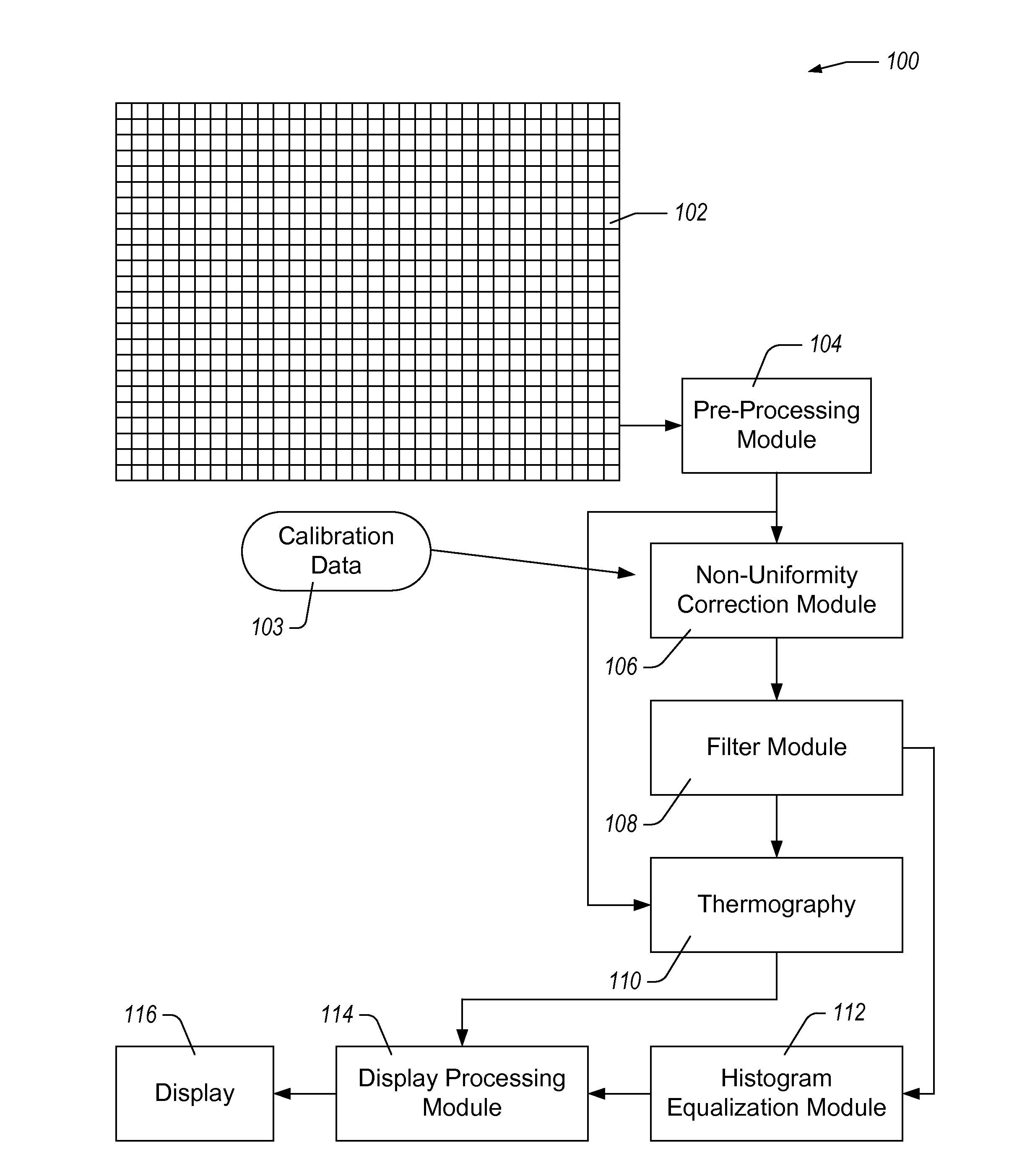
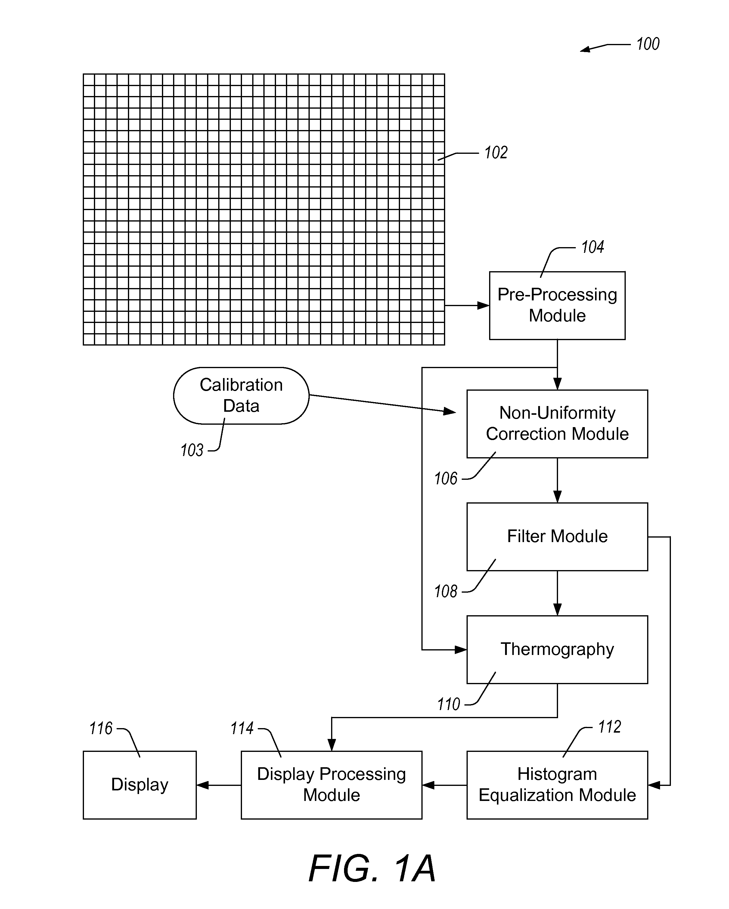
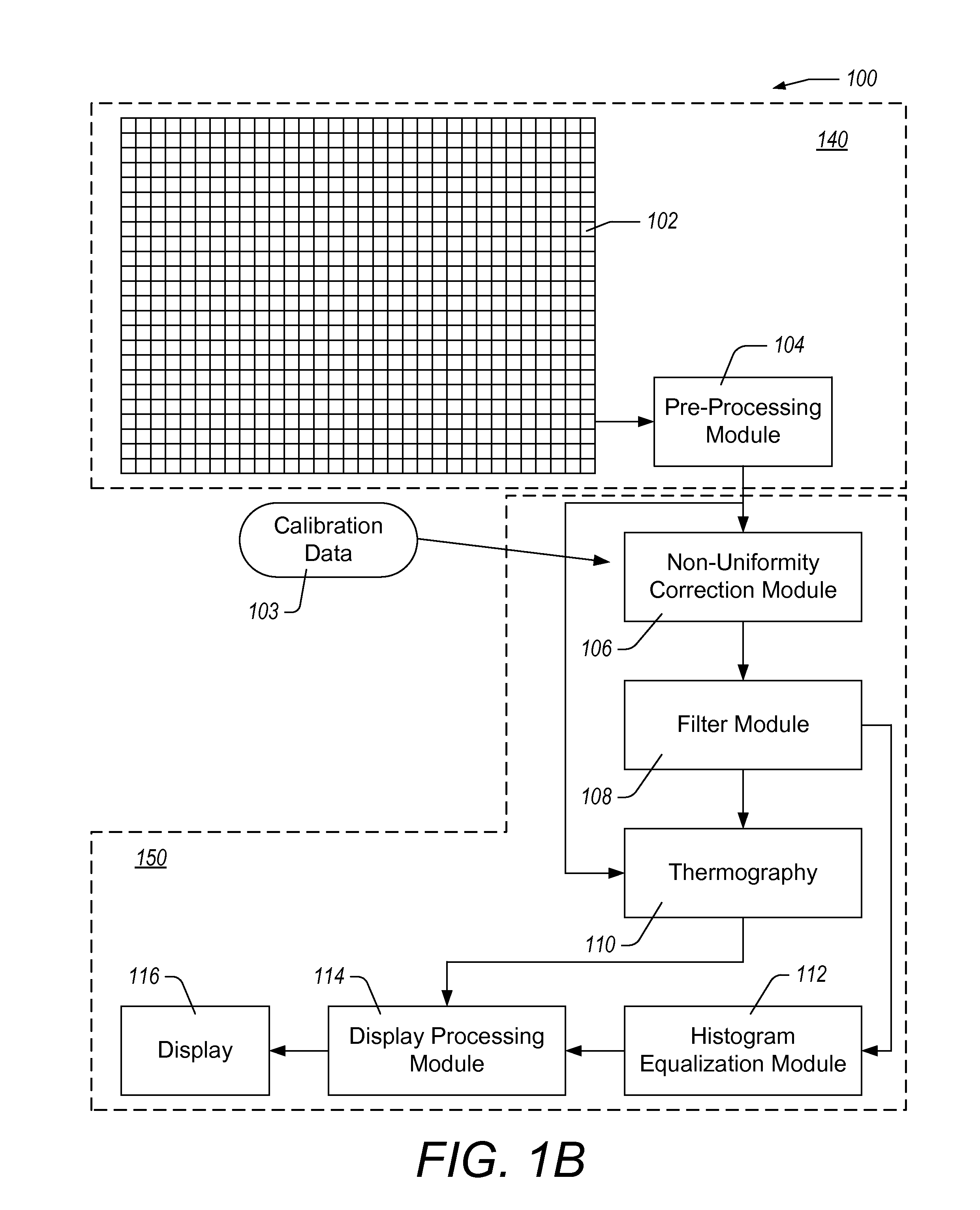
[0028]FIG. 1A illustrates a functional block diagram of an imaging system 100 comprising an image sensor such as a focal plane array 102, a pre-processing module 104, a non-uniformity correction module 106, a filter module 108, a thermography module 110, a histogram equalization module 112, a display processing module 114, and a display 116. The focal plane array 102 can output a sequence of frames of intensity data (e.g., images, thermal images, etc.). Each frame can include an array of pixel values, each pixel value representing light intensity detected by a corresponding pixel on the focal plane array 102. The pixel values can be read out of the focal plane array 102 as a stream of serial digital data. In some embodiments, the pixel values are read out of the focal plane array 102 using read out electronics that process whole rows or whole columns of the focal plane array 102. The format of the stream of data can be configured to conform to a desired, standard, or pre-defi...

example method

for Adjusting an Acquired Image Using Predicted Pixel Offset Values

[0068]FIG. 7 illustrates a flow chart of an example method 700 for adjusting an acquired image using predicted pixel offset values. The method 700 can be implemented using one or more hardware components in an imaging system or image processing system. For ease of description, the method 700 will be described as being performed by the imaging system 100 described herein with reference to FIGS. 1A and 1B. However, one or more of the steps of the method 700 can be performed by any module or combination of modules in the imaging system 100. Similarly, any individual step can be performed by a combination of modules in the imaging system 100.

[0069]In block 705, the imaging system acquires image data from an imaging array with a shutter occluding the imaging array at a first time, t1. The flat field data acquired at the first time can be stored in a permanent or temporary data storage. In block 710, the imaging system acq...


PUM


Abstract

A method for offset correction in an imaging system comprising acquiring image data representative of at least a portion of a frame of pixel intensity values from the detector array at two times with a shutter closed. The method includes determining an offset value function for individual pixels based on the image data acquired with the shutter closed. The method includes acquiring subsequent scene image data with the shutter open, and adjusting the scene image data relative to the flat field as predicted by the offset value function at the time the scene image data was acquired to correct for offset drift of the imaging system. In some embodiments, the imaging array is an infrared Focal Plane Array (IR FPA) in a thermal imaging camera.

Description

CROSS-REFERENCE TO RELATED APPLICATIONS[0001]This application claims the benefit of priority to U.S. Prov. Pat. App'n No. 62 / 033,374, filed Aug. 5, 2014, entitled “Time Based Offset Correction for Imaging Systems,” which is incorporated by reference herein in its entirety.BACKGROUND[0002]1. Field[0003]The present disclosure generally relates to offset correction for imaging systems, such as cameras including infrared cameras, and in particular to systems and methods for correcting pixel offsets as a function of time.[0004]2. Description of Related Art[0005]The increasing availability of high-performance, low-cost uncooled infrared imaging devices, such as bolometer focal plane arrays (FPAs), is enabling the design and production of mass-produced, consumer-oriented infrared (IR) cameras capable of quality thermal imaging. Such thermal imaging sensors have long been expensive and difficult to produce, thus limiting the employment of high-performance, long-wave imaging to high-value in...

Claims


Application Information

Patent Timeline
Patent Type & Authority Applications(United States)
IPC IPC(8): H04N17/00H04N5/235H04N5/33H04N5/365
CPCH04N17/002H04N5/3651H04N5/33H04N5/2353H04N23/661H04N23/73H04N25/671H04N25/68H04N25/63
Inventor CHAHINE, ROMEOPARRISH, WILLIAM J.
Owner SEEK THERMAL
Why Eureka
Try Eureka