Substrate treatment apparatus, and substrate treatment method

a substrate treatment and treatment method technology, applied in the direction of chemistry apparatus and processes, cleaning processes and apparatus, cleaning using liquids, etc., can solve problems such as accidental mixing of chemical liquids

Active Publication Date: 2016-02-18
DAINIPPON SCREEN MTG CO LTD
View PDF6 Cites 15 Cited by
  • Summary
  • Abstract
  • Description
  • Claims
  • Application Information

AI Technical Summary

Benefits of technology

[0014]Where the cleaning liquid is supplied to the cup inner wall and / or the base wall surface in the second chemical liquid supplying step and / or after the second chemical liquid supplying step, the second chemical liquid can be removed from the cup inner wall and / or the base wall surface by the supply of the cleaning liquid. At the start of the first chemical liquid supplying step for the next substrate treatment, therefore, the second chemical liquid remains neither on the cup inner wall nor on the base wall surface. This reliably prevents the first chemical liquid and the second chemical liquid from being accidentally brought into contact with each other or mixed together in the first chemical liquid supplying step.
[0015]Thus, even if the plural types of chemical liquids (the first chemical liquid and the second chemical liquid) to be used in combination for the substrate treatment are inappropriate for mixing thereof, the substrate treatment apparatus can reliably prevent the accidental mixing of the chemical liquids and complete the substrate treatment in the single treatment chamber.

Problems solved by technology

Even if plural types of chemical liquids to be used in combination for the substrate treatment are inappropriate for mixing thereof, it is sometimes desirable to complete the substrate treatment in the single treatment chamber for improvement of the productivity.
Where the treatment is performed with the use of the inappropriate combination of the chemical liquids in the single treatment chamber and the chemical liquids are received in the same vat, there is a possibility that the accidental mixing of the chemical liquids occurs on the upper surface of the vat.

Method used


Image

  • Substrate treatment apparatus, and substrate treatment method
  • Substrate treatment apparatus, and substrate treatment method
  • Substrate treatment apparatus, and substrate treatment method

Examples


first embodiment

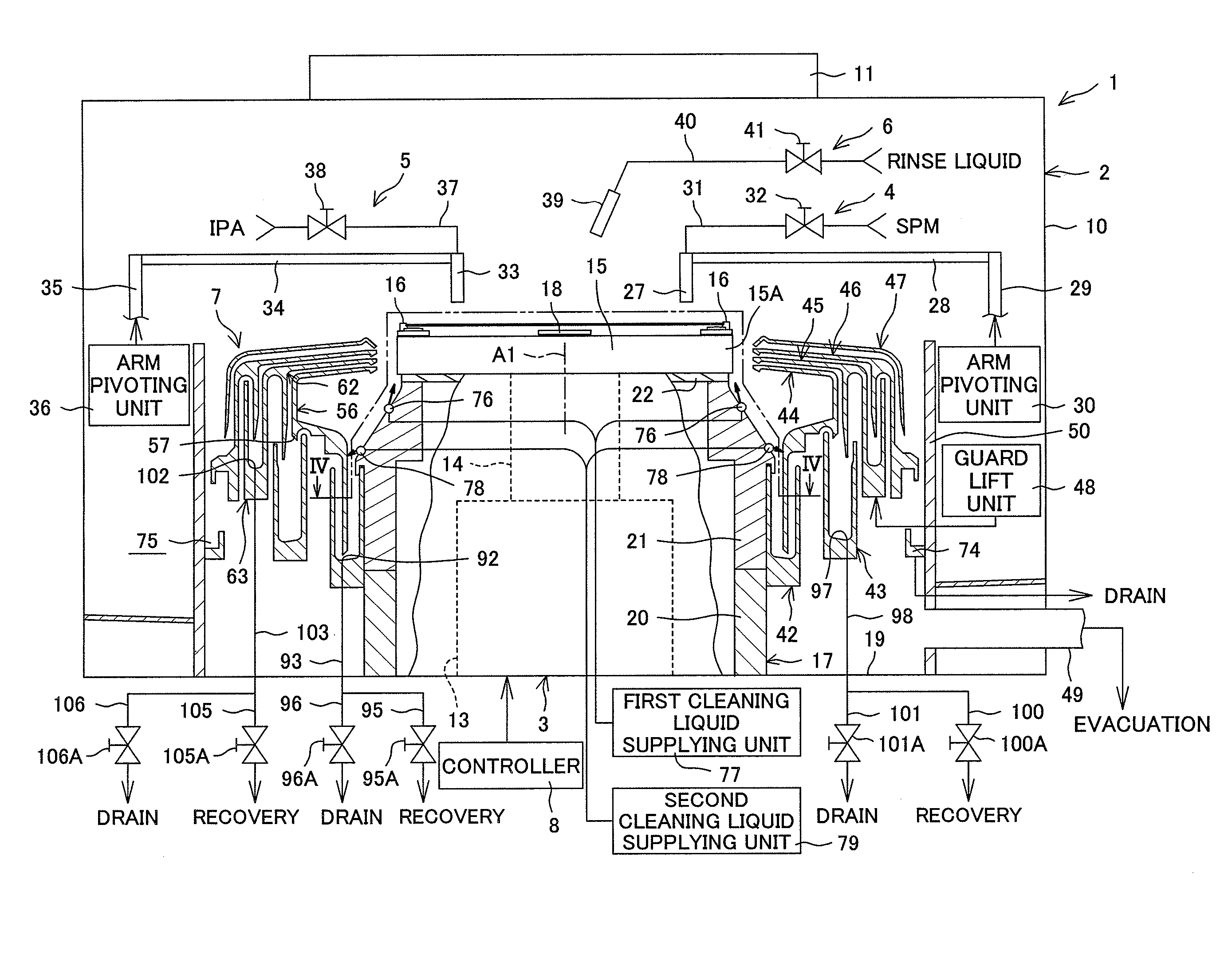
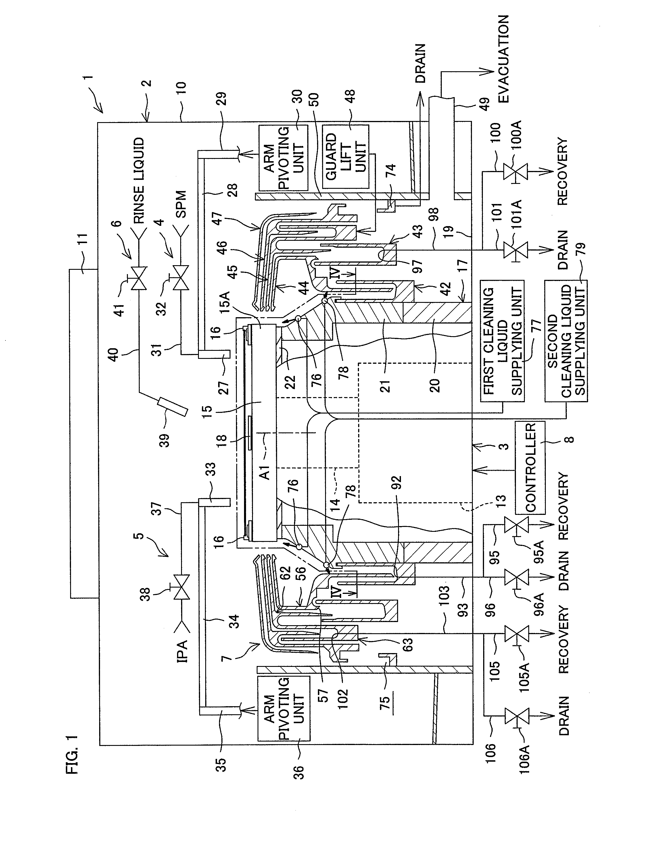
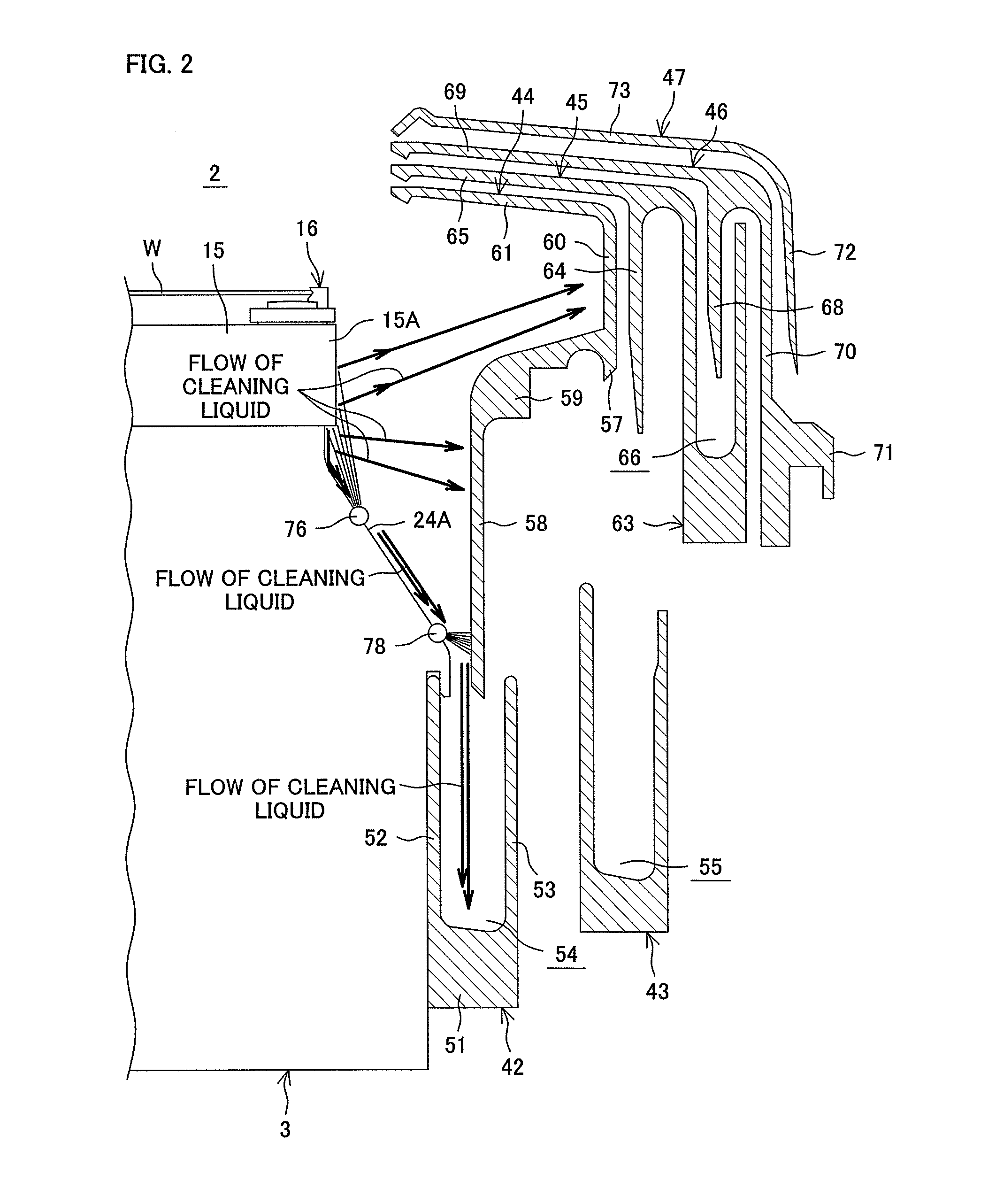
[0082]FIG. 1 is a diagram of a substrate treatment apparatus 1 according to the present invention as seen in a horizontal direction. FIGS. 2 and 3 are sectional views for explaining first and second cleaning nozzles 76, 78. FIG. 2 illustrates a state with a first guard 44 in opposed relation to a peripheral surface of a substrate W, while FIG. 3 illustrates a state with a fourth guard 47 in opposed relation to the peripheral surface of the substrate W. FIG. 4 is a sectional view taken along a sectional plane IV-IV in FIG. 1. FIG. 5 is a sectional view of a boss 21 taken along a sectional plane V-V in FIG. 4.

[0083]The substrate treatment apparatus 1 is of a single substrate treatment type adapted to treat a front surface (having a device formation region) of a substrate W (e.g., a round semiconductor wafer or the like) with a liquid for a cleaning process or an etching process. The substrate treatment apparatus 1 includes a box-shaped treatment chamber 2 having an inside space, a spi...

second embodiment

[0168]FIG. 8 is a diagram of a substrate treatment apparatus 201 according to the present invention as seen in a horizontal direction. FIG. 9 is a diagram showing the inside of a treatment chamber 202 taken along a sectional plane IX-IX in FIG. 8. FIG. 10 is a sectional view showing the inside of the treatment chamber 202 taken along a sectional plane X-X in FIG. 8.

[0169]The substrate treatment apparatus 201 is of a single substrate treatment type adapted to treat a front surface (having a device formation region) of a substrate W (e.g., a round semiconductor wafer or the like) with a liquid for a cleaning process or an etching process. The substrate treatment apparatus 201 includes a box-shaped treatment chamber 202 having an inside space, a spin chuck (substrate holding mechanism) 203 which horizontally holds a single substrate W in the treatment chamber 202 and rotates the substrate W about a vertical rotation axis A1 extending through the center of the substrate W, a sulfuric ac...

third embodiment

[0245]FIG. 17 is a schematic diagram showing the upper portion of the treatment chamber 202 according to the present invention. FIG. 18 is a schematic diagram showing the bottom portion of the treatment chamber 202 shown in FIG. 17.

[0246]A substrate treatment apparatus 301 including the treatment chamber 202 according to the third embodiment of the present invention is different from the substrate treatment apparatus 201 according to the second embodiment in that an alkaline chemical liquid supplying unit 290 is further provided which supplies SC1 (ammonia / hydrogen peroxide liquid mixture) as an exemplary alkaline chemical liquid (third chemical liquid) to the substrate W held by the spin chuck 203. In the third embodiment, three types of chemical liquids are usable.

[0247]In the third embodiment, another partition wall 302 is provided in addition to the two partition walls 257 between the tubular wall 250 and the side walls 215. That is, the third embodiment differs from the second ...


PUM


Abstract

The inventive substrate treatment apparatus includes: a rotative treatment control unit which controls a first chemical liquid supplying unit and a second chemical liquid supplying unit to perform a first chemical liquid supplying step of supplying a first chemical liquid to a substrate rotated by a substrate holding and rotating mechanism and a second chemical liquid supplying step of supplying a second chemical liquid to the substrate rotated by the substrate holding and rotating mechanism after the first chemical liquid supplying step; and a cleaning control unit which controls the cleaning liquid supplying unit to spout the cleaning liquid from the cleaning liquid outlet port to supply the cleaning liquid to the cup inner wall and/or the base wall surface before start of the second chemical liquid supplying step after end of the first chemical liquid supplying step, and/or during and/or after the second chemical liquid supplying step.

Description

BACKGROUND OF THE INVENTION[0001]1. Field of the Invention[0002]The present invention relates to a substrate treatment apparatus and a substrate treatment method for treating a substrate with a chemical liquid. Examples of the substrate to be treated include semiconductor wafers, substrates for liquid crystal display devices, substrates for plasma display devices, substrates for FED (Field Emission Display) devices, substrates for optical disks, substrates for magnetic disks, substrates for magneto-optical disks, substrates for photo masks, ceramic substrates and substrates for solar cells.[0003]2. Description of the Related Art[0004]In production processes for semiconductor devices and liquid crystal display devices, a substrate treatment apparatus of a single substrate treatment type adapted to treat a single substrate at a time is used for treating a front surface of a substrate such as a semiconductor wafer or a liquid crystal display panel glass substrate with a chemical liquid...

Claims


Application Information

Patent Timeline
Patent Type & Authority Applications(United States)
IPC IPC(8): B08B3/02
CPCB08B3/02H01L21/67051B08B9/28B08B3/022B08B3/041B08B3/08
Inventor AOMATSU, AKIYOSHIUEMAE, SHOJINAKAMURA, KAZUKIIZUMI, YOSHINORITANAHASHI, NOBUTAKA
Owner DAINIPPON SCREEN MTG CO LTD
Why Eureka
Try Eureka