Method and apparatus for hierarchical data unit-based video encoding and decoding comprising quantization parameter prediction

a hierarchical data unit and video encoding technology, applied in the field of video encoding and decoding, can solve the problems of loss of information, increased compression rate, and inability to perfectly restore original data

Active Publication Date: 2016-02-18
SAMSUNG ELECTRONICS CO LTD
View PDF9 Cites 6 Cited by
  • Summary
  • Abstract
  • Description
  • Claims
  • Application Information

AI Technical Summary

Benefits of technology

[0080]Thus, if an image having a high resolution or a large data amount is encoded in a conventional macroblock, a number of macroblocks per picture excessively increases. Accordingly, a number of pieces of compressed information generated for each macroblock increases, and thus it is difficult to transmit the compressed information and data compression efficiency decreases. However, by using the video encoding apparatus 100, image compression efficiency may be increased because a coding unit is adjusted while considering characteristics of an image while increasing a maximum size of a coding unit while considering a size of the image.
[0094]Accordingly, even if image data has a high resolution and a large amount of data, the image data may be efficiently decoded and restored by using a size of a coding unit and an encoding mode, which are adaptively determined according to characteristics of the image data, by using information about an optimum encoding mode received from an encoder.
[0099]If a resolution is high or a data amount is large, a maximum size of a coding unit may be large, so as to not only increase encoding efficiency but also to accurately reflect characteristics of an image. Accordingly, the maximum size of the coding unit of the video data 310 and 320 having the higher resolution than the video data 330 may be 64.
[0214]According to the above-described WPP, in an entropy encoding process, an LCU of each thread may determine a probability model for entropy encoding after an upper right LCU is completely entropy-encoded. However, from among syntax elements to be entropy-encoded, syntax cu_qp_delta indicating a difference between a QP and a predicted QP QP_Pred may not be directly entropy-encoded. This is because the predicted QP QP_Pred should be obtained to determine the difference between the QP and the predicted QP QP_Pred and uses a QP determined in a previously processed coding unit according to, for example, a raster scan order. In more detail, referring to FIG. 19, a predicted QP QP_Pred of an LCU 1903 may be predicted as a QP of an LCU 1905 previously processed according to a raster scan order, or a QP determined in a quantization process of an LCU 1904 previously processed in the same thread. In any case, entropy encoding of the LCU 1903 may be performed only after the LCU 1905 previously processed according to a raster scan order or the LCU 1904 previously processed in the same thread is completely encoded. As described above, if a predicted QP is obtained based on a QP of a previous coding unit, processing may be delayed until the previous coding unit is processed and thus a bottleneck problem may be generated. Accordingly, if a predicted QP is obtained based on a QP of a previous coding unit, overall performance of parallel processing may be reduced.

Problems solved by technology

Due to the quantization process, information is loss-compressed.
Because all lossy compression technologies include a quantization process, original data may not be perfectly restored but a compression rate may be increased.
According to aspects of the exemplary embodiments, a predicted quantization parameter (QP) of an initially quantized or inversely quantized data unit may be obtained based on encoding information of an upper data unit regardless of a processing order of coding units, and thus a bottleneck problem in which processing of a data unit is delayed until another data unit is completely processed according to a processing order of data units may be solved in a quantization or inverse quantization process.

Method used


Image

  • Method and apparatus for hierarchical data unit-based video encoding and decoding comprising quantization parameter prediction
  • Method and apparatus for hierarchical data unit-based video encoding and decoding comprising quantization parameter prediction
  • Method and apparatus for hierarchical data unit-based video encoding and decoding comprising quantization parameter prediction

Examples


Embodiment Construction

[0043]Hereinafter, the exemplary embodiments will be described in detail with reference to the attached drawings.

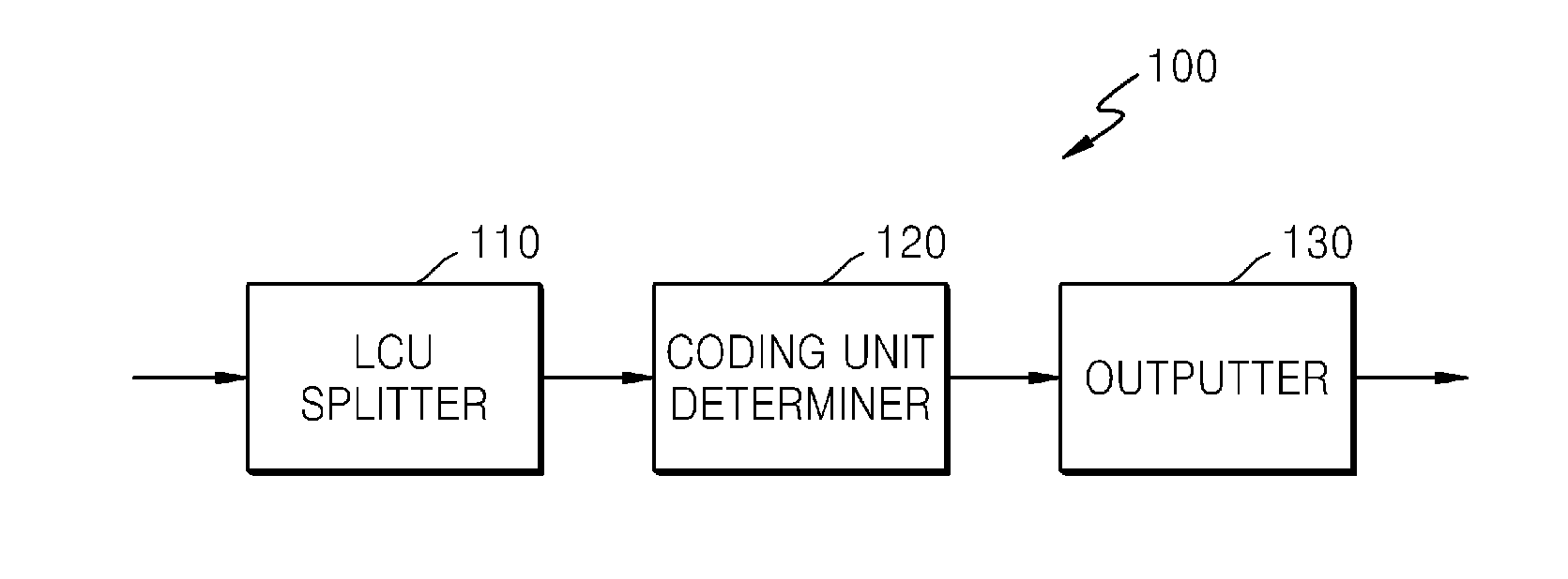
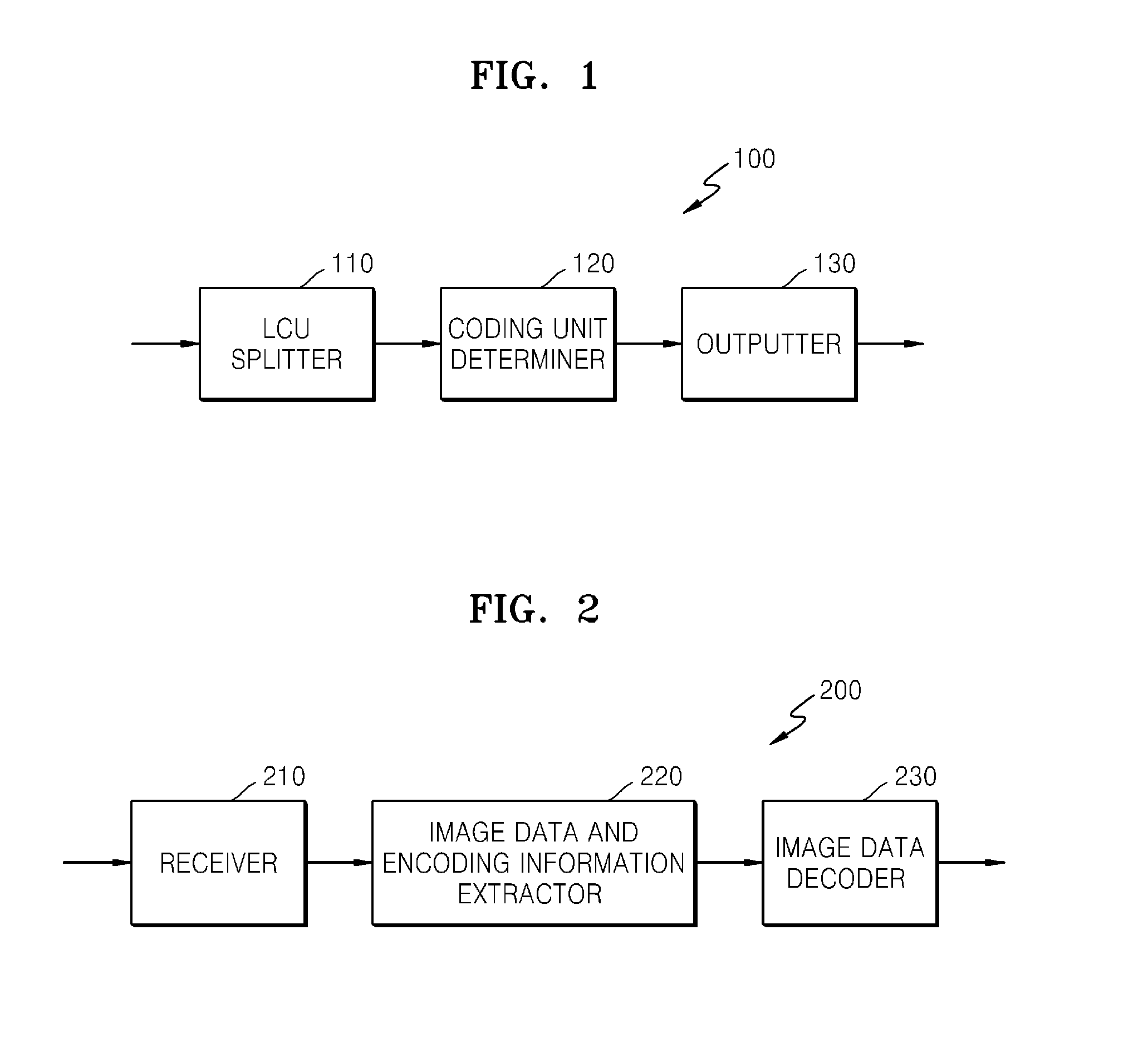
[0044]FIG. 1 is a block diagram of a video encoding apparatus 100 according to an exemplary embodiment.

[0045]The video encoding apparatus 100 includes a largest coding unit (LCU) splitter 110, a coding unit determiner 120, and an outputter 130.

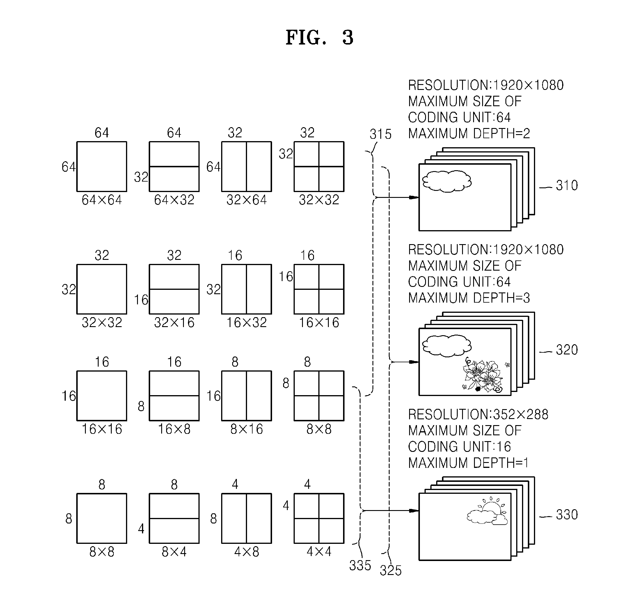
[0046]The LCU splitter 110 may split a current picture of an image based on an LCU, which is a coding unit of a maximum size. If the current picture is larger than the LCU, image data of the current picture may be split into at least one LCU. The LCU may be a data unit having a size of 32×32, 64×64, 128×128, 256×256, etc., wherein a shape of the data unit is a square which has a width and length of 2n and is greater than 8. The image data may be output to the coding unit determiner 120 according to each LCU.

[0047]A coding unit may be characterized by a maximum size and a depth. The depth denotes the number of times the coding unit i...


PUM


Abstract

A method of decoding a video includes determining an initial value of a quantization parameter (QP) used to perform inverse quantization on coding units included in a slice segment, based on syntax obtained from a bitstream; determining a slice-level initial QP for predicting the QP used to perform inverse quantization on the coding units included in the slice segment, based on the initial value of the QP; and determining a predicted QP of a first quantization group of a parallel-decodable data unit included in the slice segment, based on the slice-level initial QP.

Description

CROSS-REFERENCE TO RELATED PATENT APPLICATION[0001]This application is a continuation application of U.S. patent application Ser. No. 14 / 446,479, filed on Jul. 30, 2014, which claims the benefits of a continuation application of International Application No. PCT / KR2013 / 000776, filed on Jan. 30, 2013, and claims the benefit of U.S. Provisional Application No. 61 / 592,577, filed on Jan. 30, 2012, in the U.S. Patent and Trademark Office, the disclosures of which are incorporated herein by reference in their entireties.BACKGROUND[0002]1. Field[0003]Methods and apparatuses consistent with exemplary embodiments relate to video encoding and decoding.[0004]2. Description of Related Art[0005]In general, according to video compression standards, such as Moving Picture Expert Group (MPEG) and H.26X, a bitstream is generated by compressing image data through prediction, transformation, quantization, and entropy encoding processes.[0006]In the prediction process, a prediction image of image data ...

Claims


Application Information

Patent Timeline
Patent Type & Authority Applications(United States)
IPC IPC(8): H04N19/124H04N19/176H04N19/61
CPCH04N19/124H04N19/61H04N19/176H04N19/463H04N19/436H04N19/70H04N19/122H04N19/13H04N19/174H04N19/184H04N19/86
Inventor LEE, TAMMY
Owner SAMSUNG ELECTRONICS CO LTD
Why Eureka
Try Eureka