Waveguide Exposure Chamber for a Micrwave Energy Applicator

a technology of applicators and exposure chambers, applied in dielectric heating circuits, electric/magnetic/electromagnetic heating, other domestic articles, etc., can solve problems such as unfavorable uniform heating of systems, and achieve the effect of improving the uniformity of exposur

Inactive Publication Date: 2016-02-18
LBP MANUFACTURING INC
View PDF1 Cites 9 Cited by
  • Summary
  • Abstract
  • Description
  • Claims
  • Application Information

AI Technical Summary

Benefits of technology

[0009]In another aspect of the invention, the waveguide comprises one or more rectangular waveguide sections each having a pair of metallic deflectors for guiding or distorting the propagating microwave E-field into a modified pattern that improves the uniformity of exposure of the conveyed articles to the microwave energy.

Problems solved by technology

Such systems do not provide uniform heating of an article that has a three-dimensional profile such as a cylindrical or conical structure.

Method used


Image

  • Waveguide Exposure Chamber for a Micrwave Energy Applicator
  • Waveguide Exposure Chamber for a Micrwave Energy Applicator
  • Waveguide Exposure Chamber for a Micrwave Energy Applicator

Examples


second embodiment

[0048]a conveyancing means is shown in FIG. 13, where only a section of a plastic linked belt is presented. A plastic linked belt can be substituted in place of the fiber glass belt described above as long as the plastic material is microwave transmissible. As seen, links “a”, “b”, and “c” are joined together to form a flexible and continuous belt that would extend through the waveguide in a similar fashion to that of the fiberglass belt. With a plastic linked belt, driven pulleys 25 and 25′ would have to include respective sprockets (not shown) on each pulley end that would align with and engage with the series of slots “d” that are formed in the plastic link belt when a multiplicity of links are joined together to form a continuous belt. It should be readily understood by those in the art how the teeth of each sprocket would interface with the slots to drive the plastic linked belt through the waveguide. Therefore, the sprockets are not shown in the drawings. The plastic belt also...

first embodiment

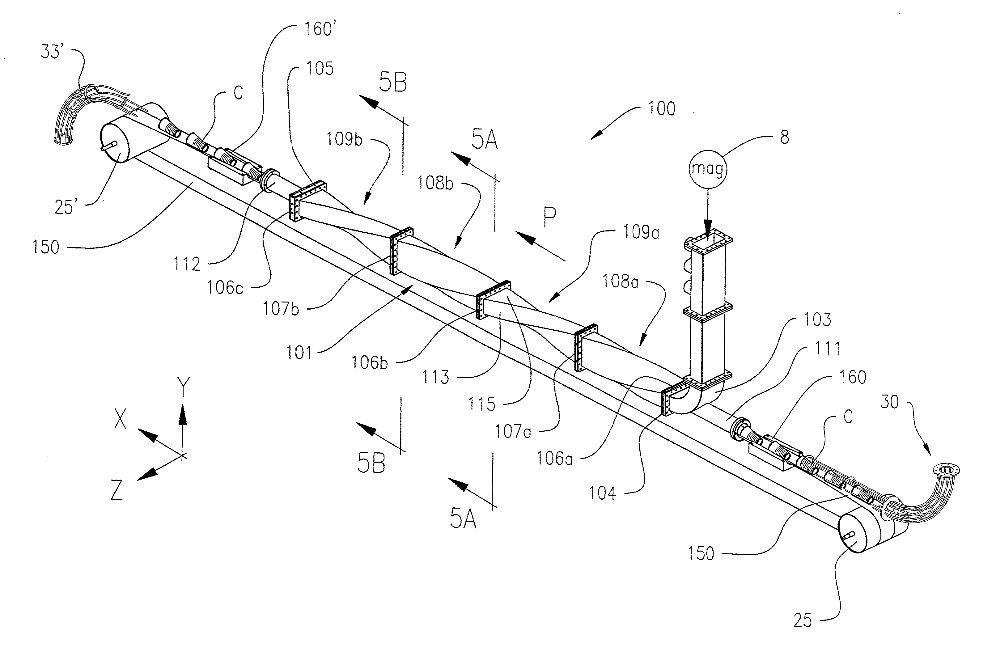
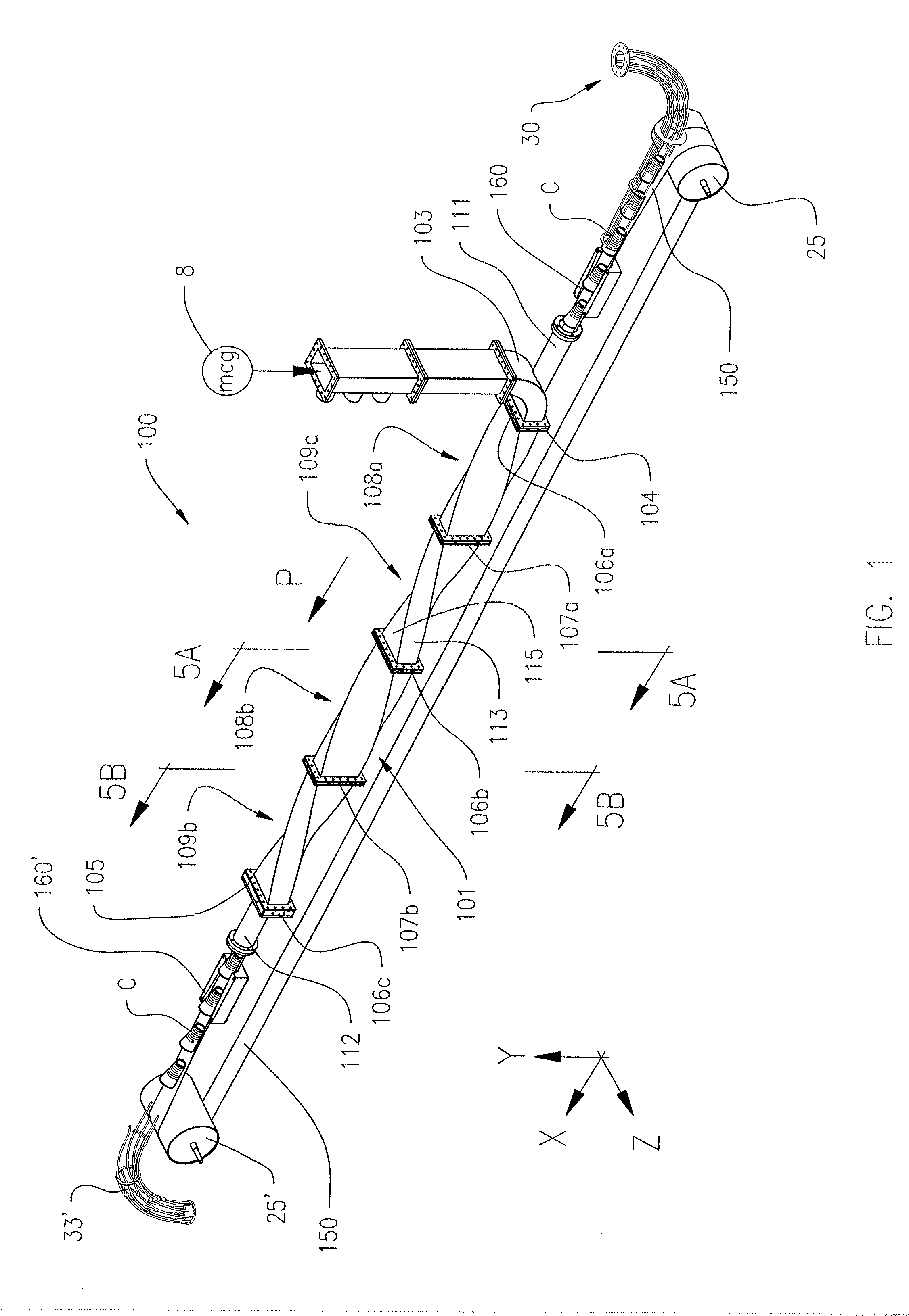
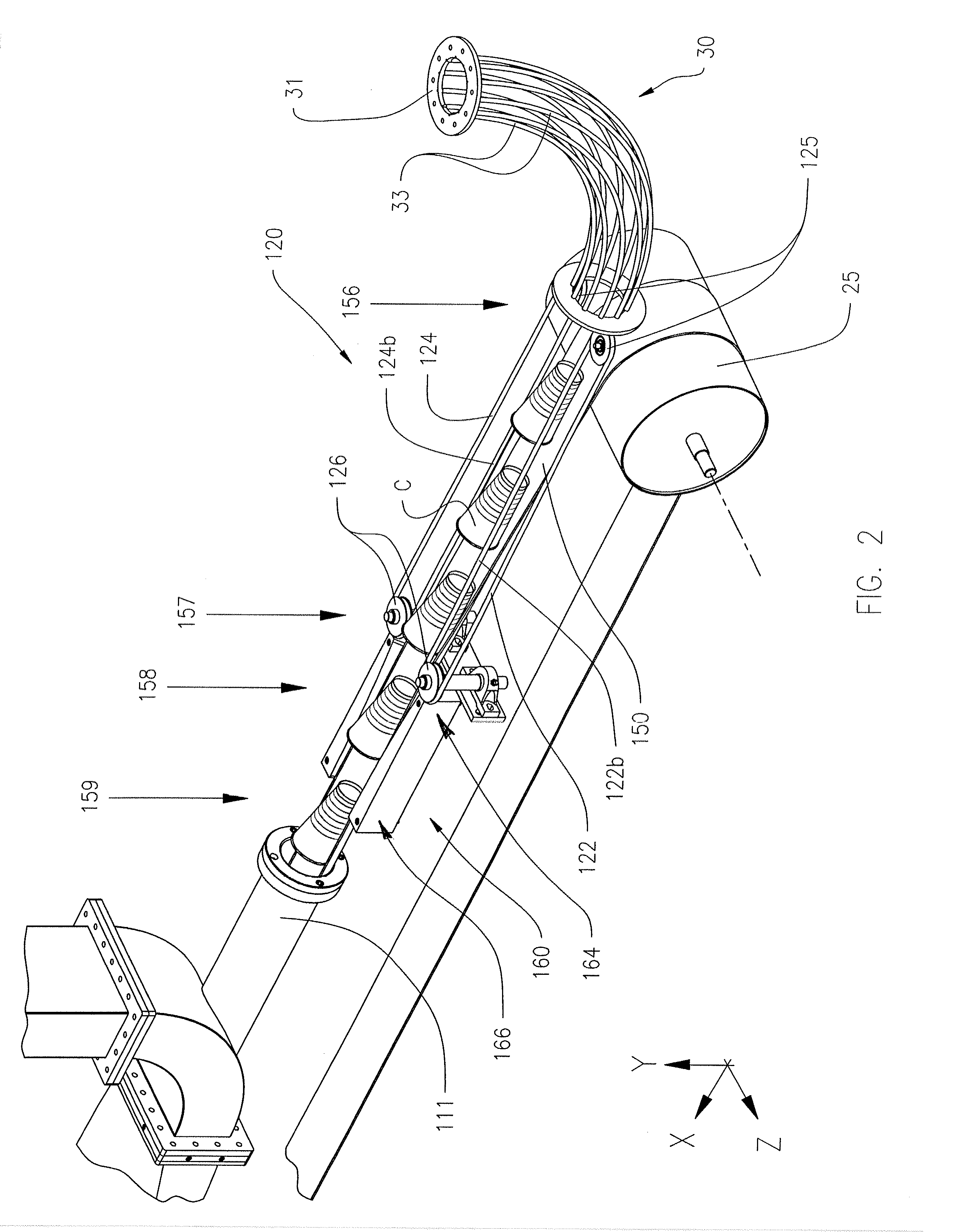
[0049]FIG. 2 shows an integral article staging system 30 for de-accelerating and depositing a unit of an untreated or non-microwaved article onto the belt 150 at the entrance end of the waveguide 102. In an example of the invention, the untreated article is a paper beverage container having a frusticonical sidewall and closed bottom, and which includes a microwave-activatable material. The article staging system 30 includes guiderails 33 that receive the containers from a pressurized, pneumatic transfer system at an in-feed end 31, and deposit the article onto the belt 150 at or between points 156 and 157. The open spaces in the guiderails 33 allow the conveying air to escape and the containers to loose velocity, thereby slowing the speed of the container. The containers can be conveyed to the article staging system 30 by other known conveying systems, including mechanical belt and gravitation conveyance. The containers can be delivered substantially continuously at a predetermined ...


PUM

PropertyMeasurementUnit
distanceaaaaaaaaaa
distanceaaaaaaaaaa
distanceaaaaaaaaaa

Abstract

A microwave heating device for activating a microwave-activatable foam insulating material within the dual sidewalls of a beverage cup. The device has a waveguide that defines an exposure chamber for the articles. The waveguide has a plurality of 90-degree twisted rectangular sections, for rotating a perpendicular microwave field pattern along the length of the waveguide. A continuous flexible belt made of a dielectric material passes into and through the exposure chamber along a conveying path, and is formed and maintained into a curled shape in cross section through the exposure chamber to retain the untreated beverage cup upon the curled belt.

Description

CROSS-REFERENCE TO RELATED APPLICATION[0001]This application claims the benefit of co-pending U.S. Provisional Application No. 62 / 037,355, filed Aug. 14, 2014, the disclosure of which is incorporated by reference in its entirety.BACKGROUND OF THE INVENTION[0002]The invention relates generally to a microwave energy applicator and, more particularly, to waveguide applicators forming exposure chambers through which materials are conveyed and subjected to uniform microwave application.[0003]In many continuous-flow microwave ovens, a planar product or a planar bed of material passes through a waveguide applicator concurrently or countercurrently to the direction of wave propagation. These ovens are typically operated in either single or multimode configurations. Single mode applicators have the advantage of a very clearly defined field pattern. For example the TE10 mode provides a peak in the heating profile across the width of the waveguide applicator, midway between its top and bottom ...

Claims


Application Information

Patent Timeline
Patent Type & Authority Applications(United States)
IPC IPC(8): H05B6/68H05B6/64H05B6/70H05B6/78H05B6/80
CPCH05B6/68H05B6/6402H05B6/80H05B6/708H05B6/78H05B6/6455H05B6/701H05B6/707B29C2035/0855B29C35/0277B29L2031/7132B29C44/022
Inventor FU, THOMASSTAMATIOU, DIMITRIWASZKOWIAK, STEVEMCLEAN, DAVID
Owner LBP MANUFACTURING INC
Why Eureka
Try Eureka