Microwave ablation system

a technology of microwave ablation and catheter assembly, which is applied in the field of microwave ablation catheter assembly, can solve the problems of tissue heating along the length of the ablation catheter, loss of microwave energy along the coaxial cable, and substantial heating of the coaxial cabl

Active Publication Date: 2016-03-03
TYCO HEALTHCARE GRP LP
View PDF14 Cites 62 Cited by
  • Summary
  • Abstract
  • Description
  • Claims
  • Application Information

AI Technical Summary

Benefits of technology

[0018]An aspect of the present disclosure provides a microwave ablation system. The microwave ablation system comprises a microwave energy source, an ablation catheter, and an extended working channel. The ablation catheter includes a coaxial cable, having a proximal portion and a distal portion, and a radiator disposed at the distal portion of the coaxial cable. The coaxial cable includes an inner conductor and an outer conductor, and the proximal portion of the coaxial cable is operatively connected to the microwave energy source. The extended working channel is configured to receive the ablation catheter for positioning the radiator adjacent target tissue. The extended working channel includes an electrically conductive inner surface, wherein, upon application of microwave energy to the ablation catheter, energy conducted along the outer conductor of the coaxial cable is captured within the conductive inner surface of the extended working channel and prevented from affecting tissue adjacent the extended working channel

Problems solved by technology

As previously mentioned, the microwave ablation catheter is coupled to the microwave energy source via a feedline, often in the form of an unbalanced coaxial cable.
As a result of the coaxial cable being unbalanced, there is often a loss of microwave energy along the coaxial cable.
Additionally, substantial heating of the coaxial cable can occur during delivery of microwave energy.
The balun or choke helps to balance the coaxial cable of the microwave ablation catheter when microwave energy is transmitted to the radiating section of the microwave ablation catheter to ablate tissue and substantially impede the current flowing down the outer conductor which might lead to undesired heating of tissue along the length of the ablation catheter.
While the aforementioned microwave ablation catheters are suitable for their intended purposes, the balun on the microwave ablation catheter is added structure that increases the size of the microwave ablation catheter, which, in turn, may decrease the flexibility of the microwave ablation catheter.

Method used


Image

  • Microwave ablation system
  • Microwave ablation system
  • Microwave ablation system

Examples


Embodiment Construction

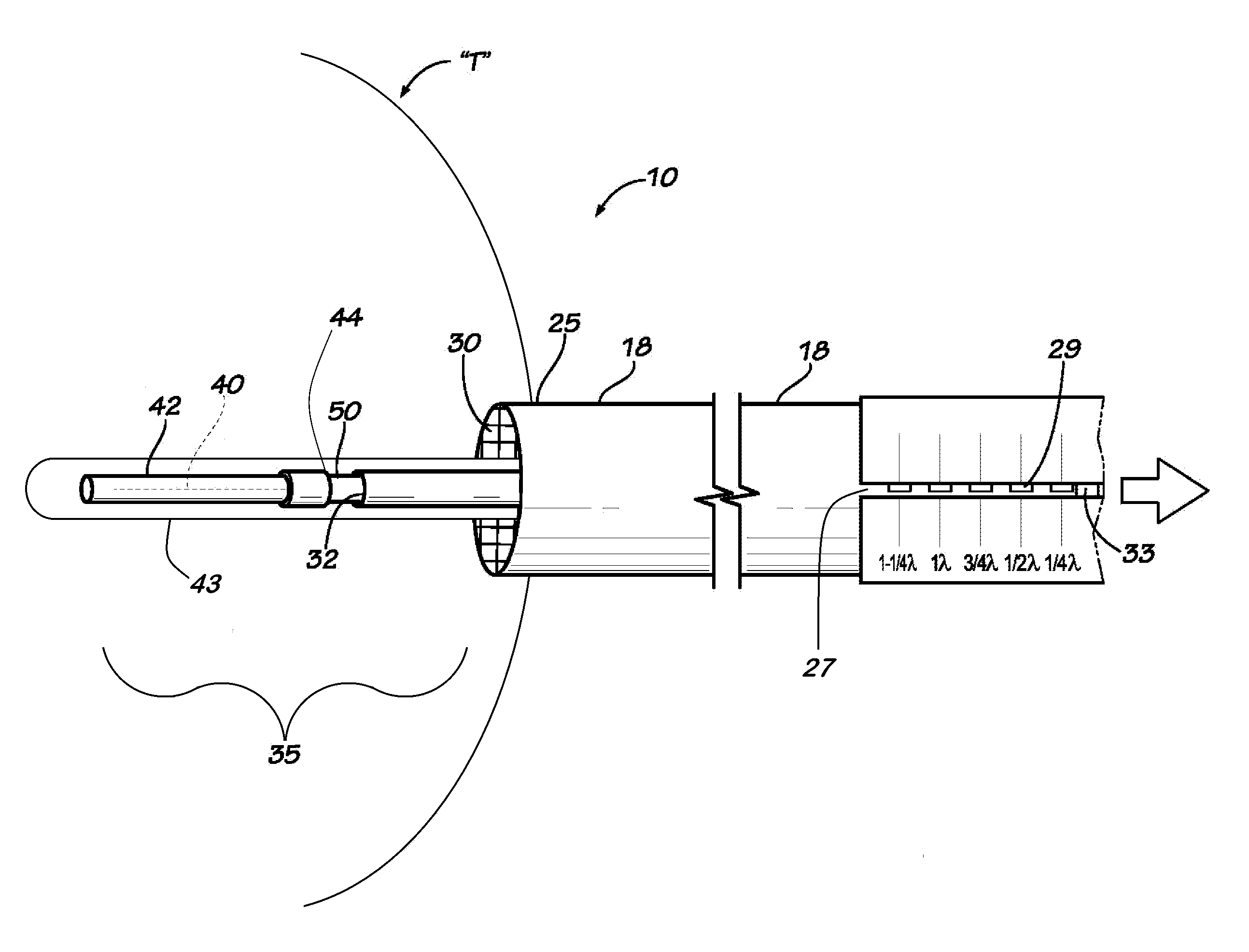
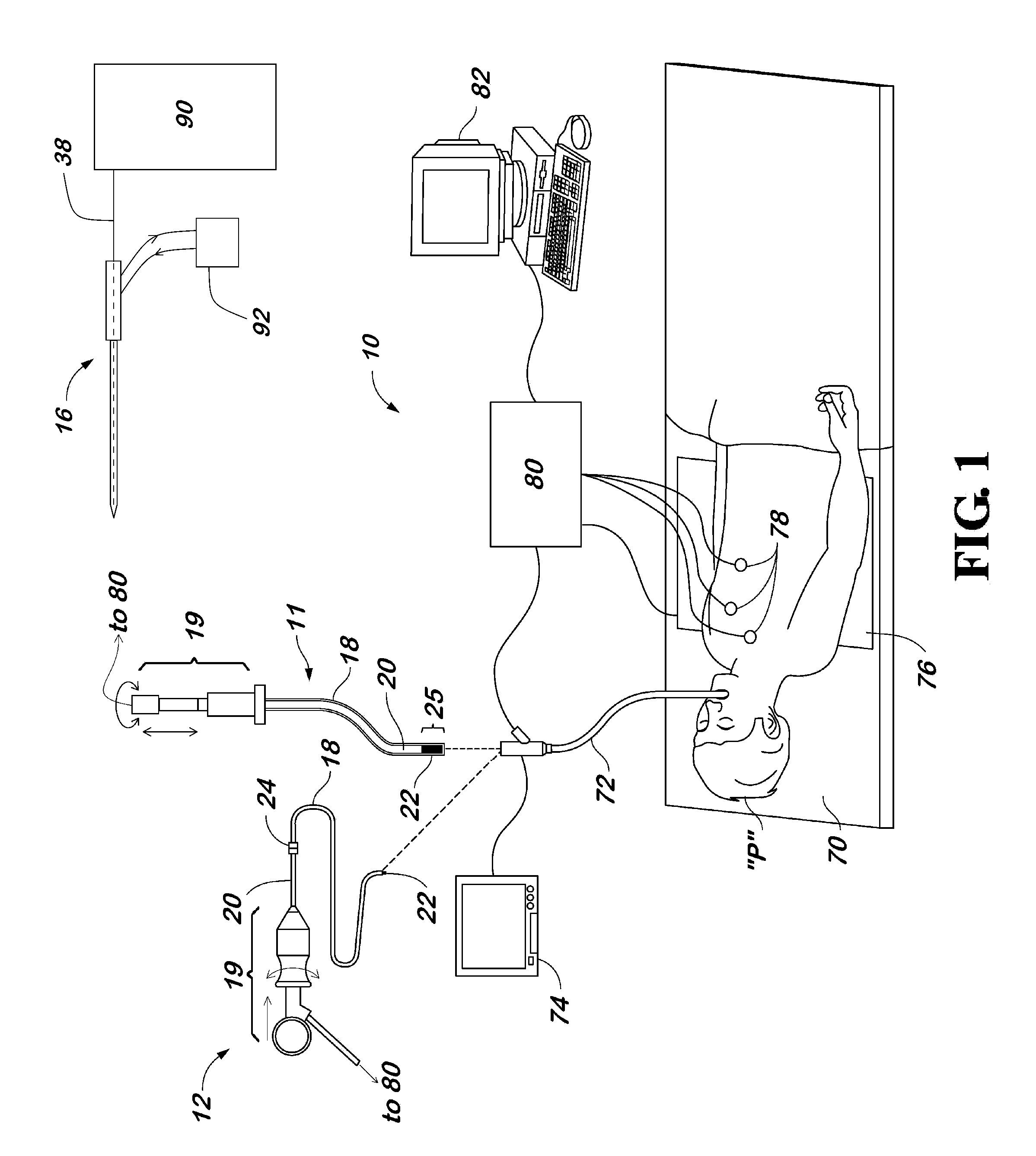
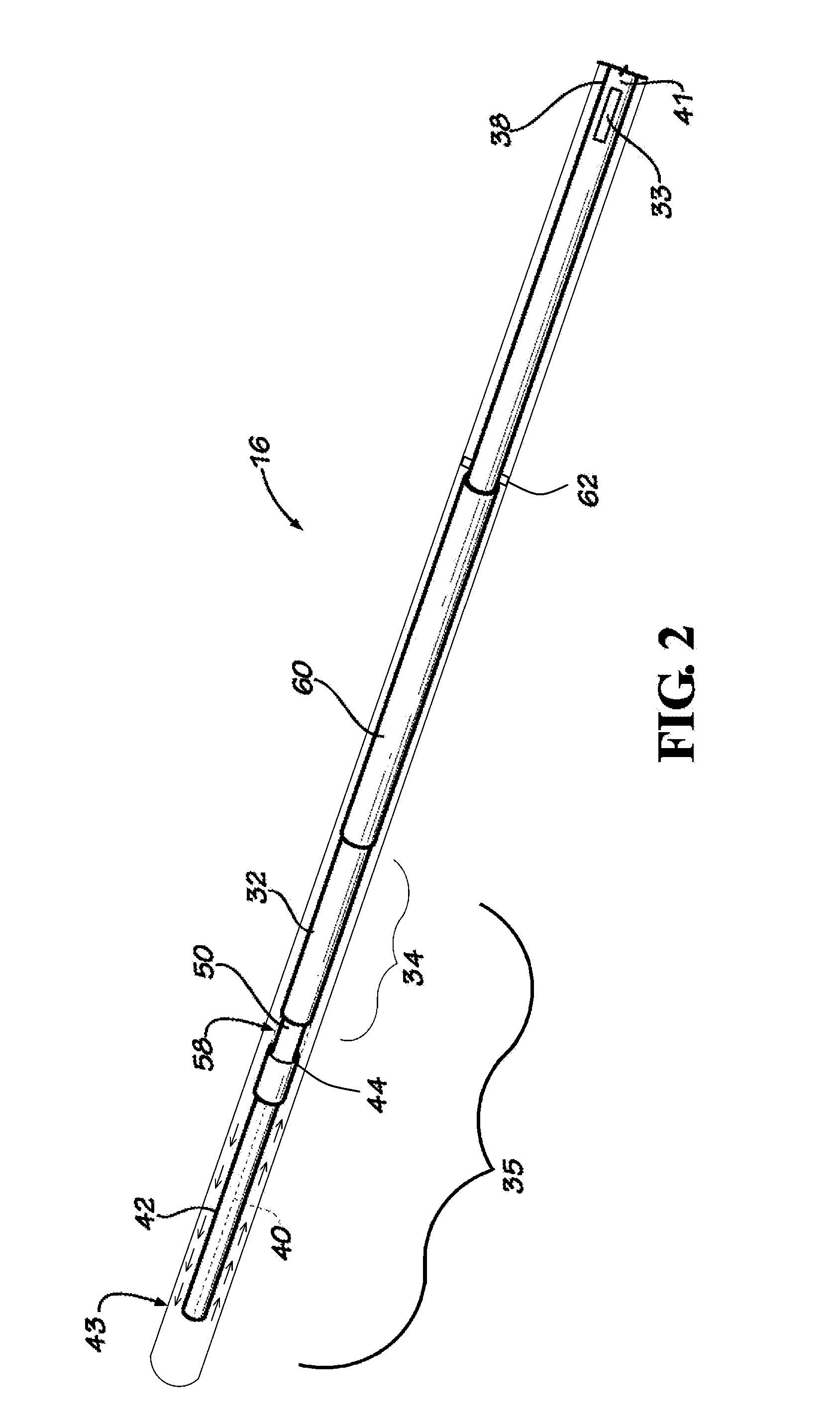
[0026]The present disclosure is directed to a microwave ablation catheter assembly and a method for placement of a microwave ablation antenna within a luminal structure such as the pathways of the bronchi in the lungs. Embodiments of the present disclosure include an un-choked microwave ablation catheter, or microwave ablation catheter without a balun. Further embodiments are directed to a microwave ablation catheter with a modified balun or choke. Still further embodiments of the present disclosure are directed to an improved microwave ablation catheter assembly having increased flexibility and a reduced number of components while providing adequate therapeutic results.

[0027]Detailed embodiments of the present disclosure are disclosed herein; however, the disclosed embodiments are merely examples of the disclosure, which may be embodied in various forms. Therefore, specific structural and functional details disclosed herein are not to be interpreted as limiting, but merely as a bas...


PUM


Abstract

A microwave ablation catheter assembly is provided. A coaxial cable configured to connect to a microwave energy source at its proximal end and at its distal end to a distal radiating section. The coaxial cable includes inner and outer conductors and a dielectric positioned therebetween. An extended working channel is configured to receive the coaxial cable for positioning the coaxial cable adjacent target tissue. At least a portion of an inner surface of the extended working channel is electrically conductive. The electrically conductive inner surface of the extended working channel may function as a balun to maintain a balanced signal between the inner and outer conductors of the coaxial cable when the distal radiating section of the coaxial cable is energized.

Description

CROSS REFERENCE TO RELATED APPLICATION[0001]The present application claims the benefit of and priority to U.S. Provisional Application Ser. No. 62 / 041,773, filed on Aug. 26, 2014, the entire contents of which are incorporated herein by reference.BACKGROUND[0002]1. Technical Field[0003]The present disclosure relates to a microwave ablation catheter assembly. More particularly, the present disclosure relates to a microwave ablation catheter assembly including an extended working channel having an electrically conductive inner surface that functions as an electromagnetic shield or a balun for a microwave ablation catheter of the microwave ablation catheter assembly.[0004]2. Description of Related Art[0005]Microwave ablation involves the application of high-frequency electromagnetic waves for treating various maladies including tumors in of organs like the liver, brain, heart, lung and kidney. It is known that tumor cells denature at elevated temperatures that are slightly lower than te...

Claims


Application Information

Patent Timeline
Patent Type & Authority Applications(United States)
IPC IPC(8): A61B18/18
CPCA61B18/1815A61B19/54A61B2018/00577A61B2018/00029A61B2018/00023A61B2018/00017A61B2018/1861A61B2018/00511A61B2018/00541A61B2034/107A61B2034/2051A61B90/39
Inventor DICKHANS, WILLIAM, J.
Owner TYCO HEALTHCARE GRP LP
Why Eureka
Try Eureka