Machining Head for a Laser Machining Device

a laser processing and laser technology, applied in the direction of laser beam welding apparatus, measurement devices, instruments, etc., can solve the problems of interference in the coherence tomograph, and achieve the effect of good distance measurement quality and easy realization

Active Publication Date: 2016-03-03
PRECITEC OPTRONIK GMBH
View PDF7 Cites 38 Cited by
  • Summary
  • Abstract
  • Description
  • Claims
  • Application Information

AI Technical Summary

Benefits of technology

[0034]When changing the focal length of the focusing optics, the focal spot of the measuring light is thus always automatically moved along therewith. At the same time, at least parts of the focusing optics can be used to focus the measuring light. Because only sufficient focusing of the measuring light, which is preferably less than four times the Rayleigh length, ensures a good quality of the distance measurement with the coherence tomograph.
[0035]Through the partial joint use of the focusing optics, it can be ensured, moreover, in a particularly simple manner, that the measuring light is always focused in the same focal plane in which the focal spot of the laser radiation is also situated. For, in general, it is particularly important to know how far the workpiece is away from the processing head at the processing point at which the focal spot of the laser radiation is formed. The measuring light generated by the coherence tomograph does not necessarily have to be directed at the focal spot. Thus, for example, it is possible to provide for the measuring light an additional scanning device which travels scanner-like over a region surrounding the processing point on the workpiece and in this way provides a three-dimensional relief of the surface. It is also possible for the measuring light beam to travel on a circular path around the processing point. Such a circular scanner arranged in the optical path of the measuring light can be realised very easily with the aid of a wobble mirror, a micromirror tiltable about two tilt axes or a rotating wedge plate. The information obtained by a circular scanner is often sufficient for seam tracking.

Problems solved by technology

Measuring light, which has been generated by a measuring light source and reflected by the workpiece, interferes in the coherence tomograph with measuring light which has traveled an optical path length in a reference arm.

Method used


Image

  • Machining Head for a Laser Machining Device
  • Machining Head for a Laser Machining Device
  • Machining Head for a Laser Machining Device

Examples


Embodiment Construction

1. Structure of the Laser Processing Device

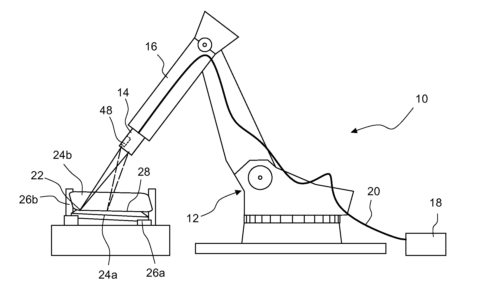
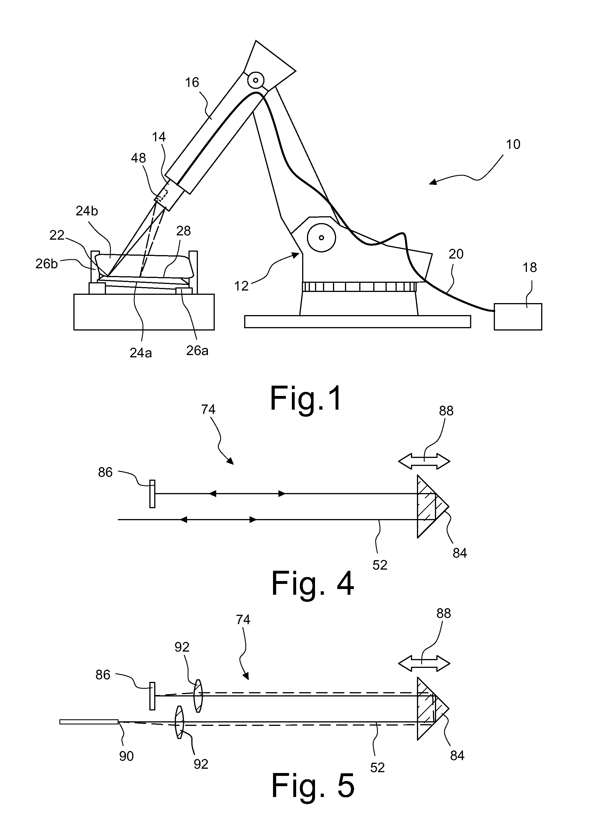
[0055]FIG. 1 shows in a schematic representation a laser processing device 10 having a robot 12 and a processing head 14 according to the invention, which is fastened to a movable arm 16 of the robot 12.

[0056]The laser processing device 10 also includes a laser radiation source 18 which is formed in the illustrated exemplary embodiment as a disc laser or fibre laser. Laser radiation 30 generated by the laser radiation source 18 is supplied via an optical fibre 20 to the processing head 14 and focused by the latter in a focal spot 22.

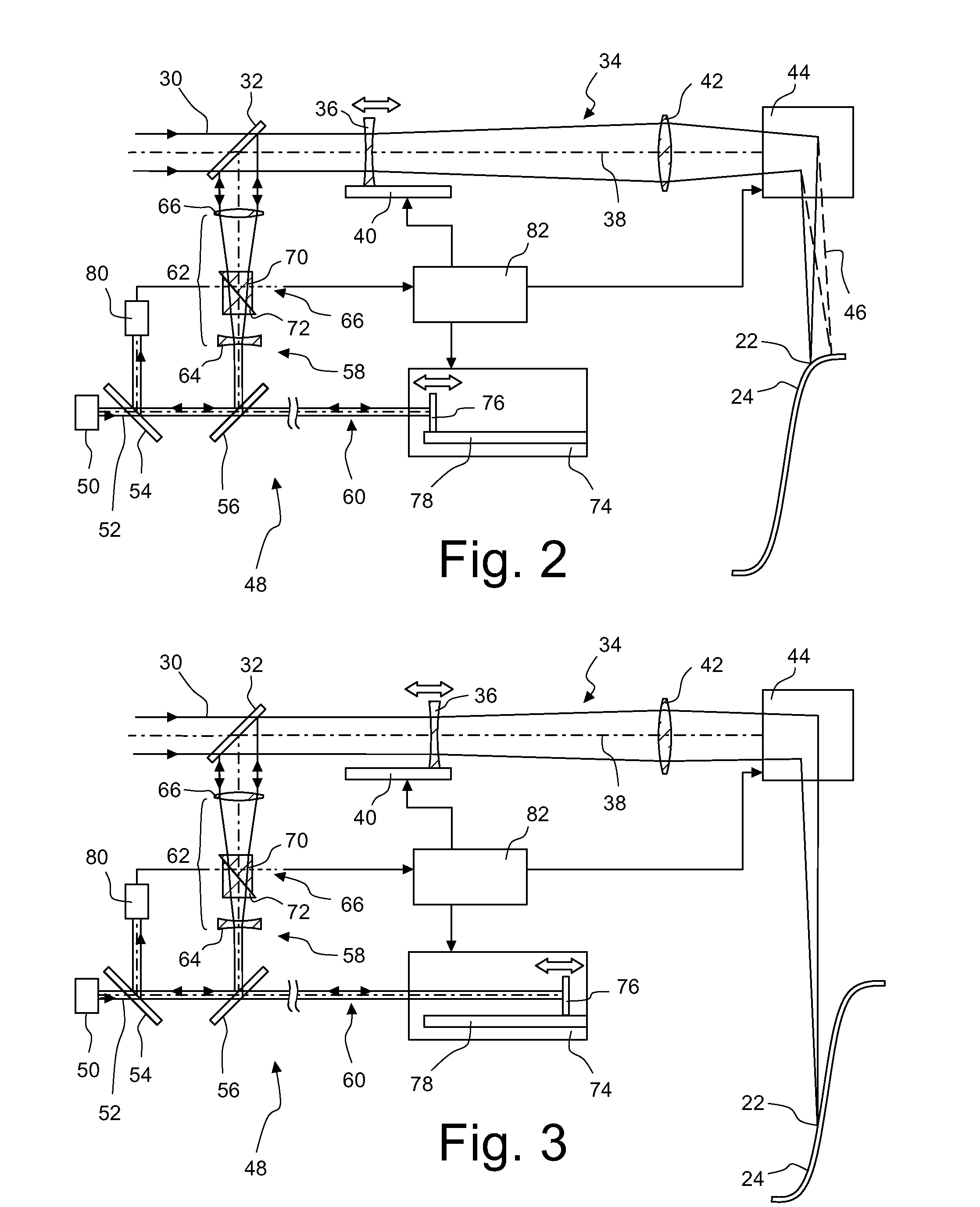
[0057]The laser processing device 10 is provided for a remote laser processing of workpieces. The distance between the focal spot 22 and the processing head 14 is therefore about 30 cm to 100 cm. As will be explained below with reference to FIG. 2, the focal length of focusing optics included in the processing head 14 is changeable in order to be able to position the focal spot 22 on the workpiece at different d...


PUM

PropertyMeasurementUnit
angleaaaaaaaaaa
angleaaaaaaaaaa
angleaaaaaaaaaa

Abstract

The invention relates to a machining head for a laser machining device, which is equipped for machining a workpiece (24) using laser radiation (30). The laser machining head comprises an adjustable focusing optical unit (34), which focuses the laser radiation (30) in a focal spot (22). The distance between the focal spot (22) and a machining head can be modified by modifying the focal length of the focusing optical unit (34). A scanning apparatus (44) deflects the laser radiation (30) in different directions. An optical coherence tomography device (48) measures a distance between the treatment head and the workpiece (24). Here, measuring light (52), which was generated by a measuring light source (50) and reflected by the workpiece (24), interferes in the coherence tomography device (48) with measuring light, which traveled an optical path length in a reference arm (60). A path-length modulator (74) is disposed in the reference arm (60) and it updates the optical path length in the reference arm (60) synchronously with, and dependent on, a change in the focal length of the focusing optical unit (34).

Description

CROSS-REFERENCE TO RELATED APPLICATIONS[0001]This is a continuation application of International Patent Application PCT / EP2014 / 001234 filed May 8, 2014 and claims benefit of prior German patent application 10 2013 008 269.2 filed May 15, 2013.BACKGROUND OF THE INVENTION[0002]1. Field of the Invention[0003]The invention relates to a processing head for a laser processing device, with which workpieces can be welded, cut or otherwise processed.[0004]2. Description of the Prior Art[0005]Laser processing devices normally comprise a laser radiation source which may, for example, be a fibre laser or a disc laser. A laser processing device further includes a processing head, which focuses the laser radiation generated by the laser radiation source in a focal spot, and a beam supply device, which supplies the laser radiation generated by the laser radiation source to the processing head. The beam supply device may comprise optical fibres or other optical waveguides and / or one or more deflect...

Claims


Application Information

Patent Timeline
Patent Type & Authority Applications(United States)
IPC IPC(8): B23K26/04B23K26/046B23K26/06
CPCB23K26/03B23K26/048G01B9/02044B23K26/082B23K26/046B23K26/0643B23K26/0665G01B9/02091G01B9/02028G01B9/02063
Inventor KOGEL-HOLLACHER, MARKUSSCHOLEBER, MARTIN
Owner PRECITEC OPTRONIK GMBH
Why Eureka
Try Eureka