
System and method for enhancing a visualization of coordinate points within a robot's working envelope

Active Publication Date: 2016-03-03
FANUC ROBOTICS NORTH AMERICA
View PDF0 Cites 3 Cited by
  • Summary
  • Abstract
  • Description
  • Claims
  • Application Information

AI Technical Summary

Benefits of technology

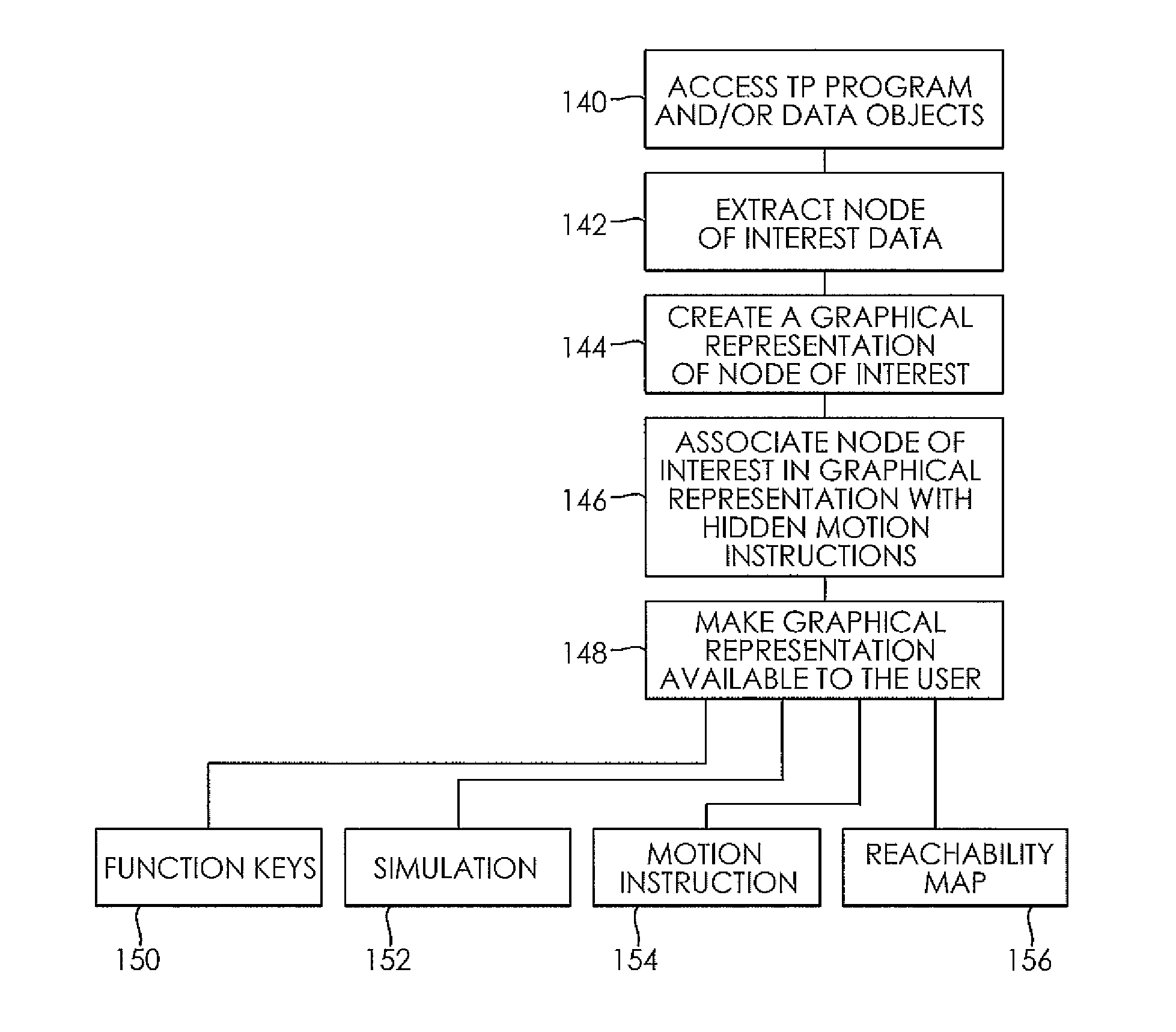
The present invention provides a system and method for enhancing the visualization of coordinate points within a robot's working envelope. This is achieved by reading part data and robot data using a teach pendant program, which automatically stores the data within a program instruction of the teach pendant program. The data may include a part offset relative to a known position. The programmable controller accesses the program instruction, extracts the data, and provides a graphical representation of the data on a display device, allowing for easier visualization and placement of the part or robot at a desired location. The system and method improve the accuracy and precision of the robot's operations.

Problems solved by technology

As an added complexity, the controlled machinery may further include a moving conveyor system that moves work (e.g. a tool or a part to be serviced by a robot) relative to such robot, requiring additional processing to determine work location relative to the robot to facilitate robotic manipulation of the work.
Programming, program verification and program touch-up are typically performed iteratively and may take significant time.
Undesirably, Cartesian conveyor tracking systems may be difficult to use primarily because robot manipulator joint angle locations can change for a given point on the part.
Moreover, there is no guarantee that the point on the work can be reached by the robot once the work has been moved.
However, such data files may be complex and quite large, so that the process of reviewing and searching the data files may require a level of expertise and may further be time consuming.
Moreover, existing simulation programs are not capable of capturing data indicative of position for a robot and associated work and using such data for synchronization of the work and the robot for planning and teaching purposes.

Method used


Image

  • System and method for enhancing a visualization of coordinate points within a robot's working envelope
  • System and method for enhancing a visualization of coordinate points within a robot's working envelope
  • System and method for enhancing a visualization of coordinate points within a robot's working envelope

Examples


Embodiment Construction

[0021]The following detailed description and appended drawings describe and illustrate various embodiments of the invention. The description and drawings serve to enable one skilled in the art to make and use the invention, and are not intended to limit the scope of the invention in any manner.

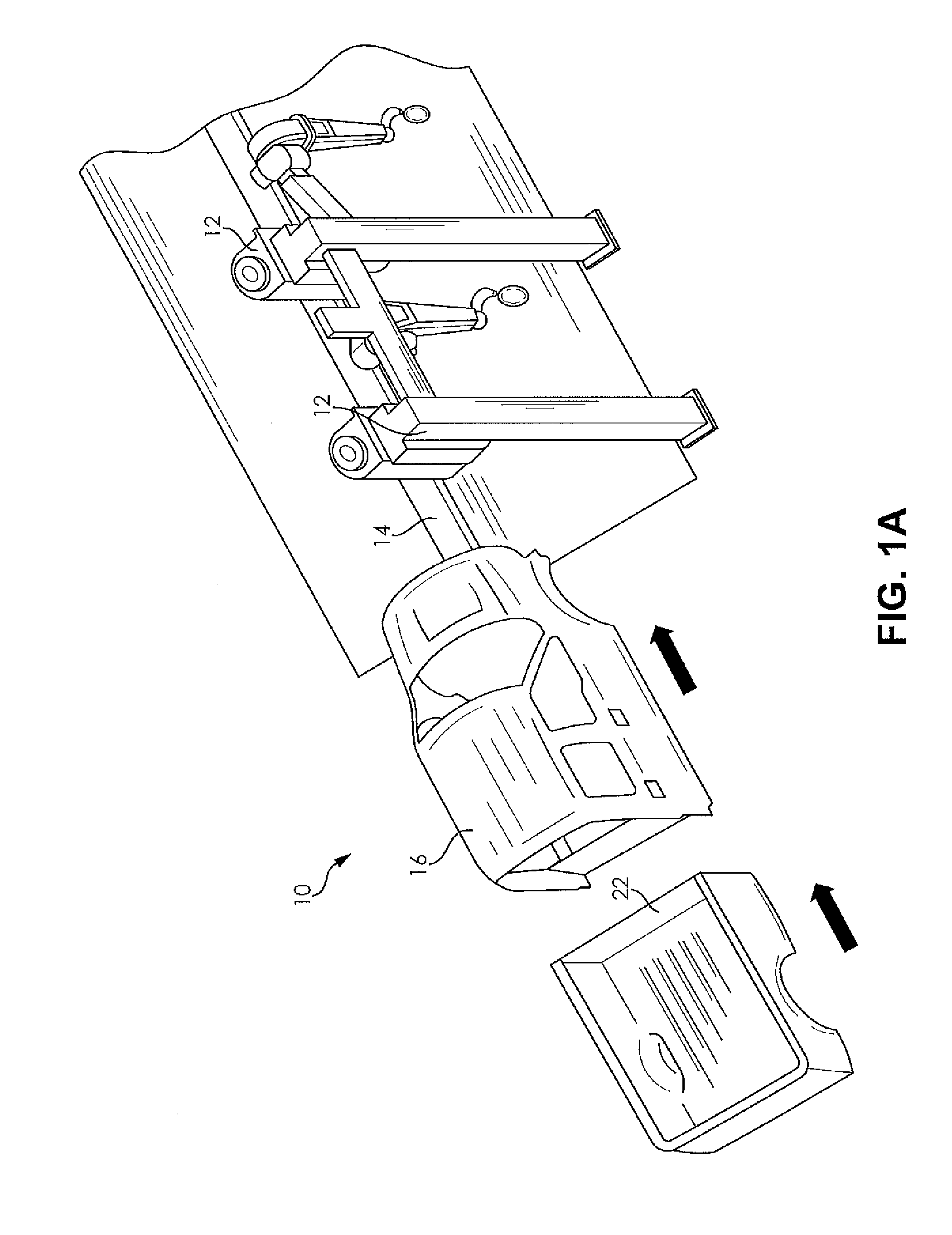
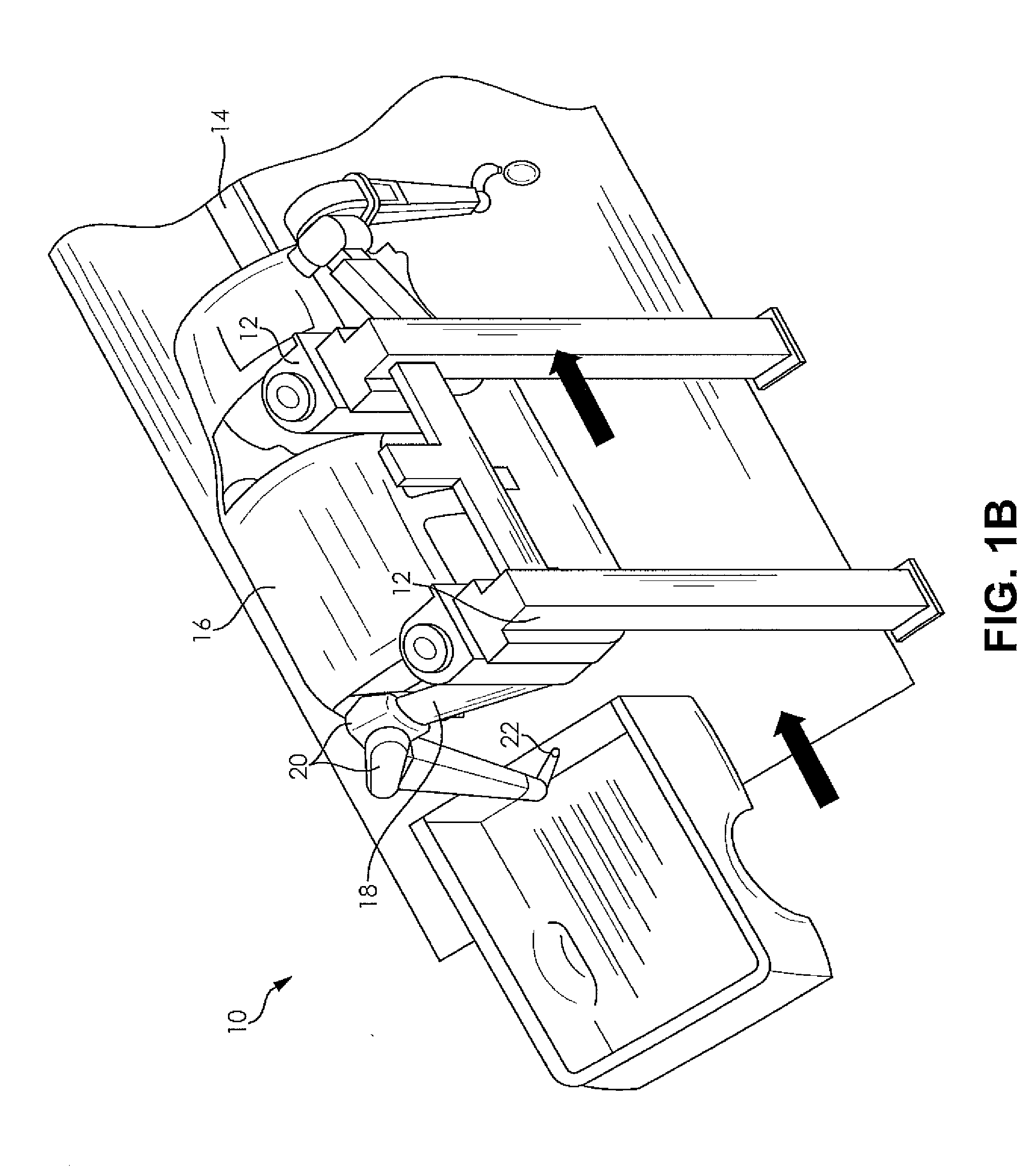
[0022]A representative work cell 10 including a robot 12 and a moving conveyor system 14 moving an item of work 16 relative to the robot 12 is described with reference to FIGS. 1A and 1B. The item of work 16 may be a part, a tool, a fixture, or any other item intended to be serviced by the robot 12. It is understood that the moving conveyor system 14 may move the item of work 16 in any dimension and direction, including rotationally, as required to allow the robot 12 to service the item of work 16. The robot 12 may include one or more articulating arms 18, each of which may include one or more joints 20 that provide pivotal, rotational or other movement relative to the item of work 16, As show...


PUM


Abstract

A system and method for enhancing a visualization of coordinate points within a robot's working envelope is disclosed. Part data associated with a position of a part, which may include part offset from a known position, is read using a teach pendant program. The part data is automatically stored within a hidden program instruction of the teach pendant program. The part data may be stored within the part program in a motion instruction associated with a motion line of the teach pendant program.

Description

FIELD OF THE INVENTION[0001]The present invention relates generally to robotic systems, and more particularly, to systems and methods for part location during operation of robotic systems including moving conveyors.BACKGROUND OF THE INVENTION[0002]Programmable controllers operate elaborate industrial equipment, such as robots, in accordance with a plurality of stored control programs. When executed, each program causes the programmable controller or robot controller to examine the state of the controlled machinery by evaluating signals from one or more sensing devices (e.g., position encoders, temperature sensors, or pressure sensors) and to operate the machinery (e.g., by controlling the output voltage for servo motors, or energizing / de-energizing discrete components) based on a procedural framework, the sensor signals and, if necessary, more complex processing. As an added complexity, the controlled machinery may further include a moving conveyor system that moves work (e.g. a too...

Claims


Application Information

Patent Timeline
IPC IPC(8): B25J9/16
CPCB25J9/1664G05B19/408
Inventor CHENG, SAI-KAIGEHEB, GORDONGIRI, NIVEDHITHAGRACA, RANDY, A.O'TOOLE, DAVID, J.
Owner FANUC ROBOTICS NORTH AMERICA
Learn More