Automatic analysis device

Active Publication Date: 2016-03-03
ROCHE DIAGNOSTICS OPERATIONS
View PDF2 Cites 0 Cited by
  • Summary
  • Abstract
  • Description
  • Claims
  • Application Information

AI Technical Summary

Benefits of technology

The present invention offers a method and device for analyzing immunity using magnetic particles. This invention helps to reduce the amount of light from areas where the density of magnetic particles on the surface of the working electrode is small. This reduces the likelihood of low signal-to-noise ratios and results in a higher overall signal-to-noise ratio. Overall, this invention improves the accuracy and reliability of immunity analysis.

Problems solved by technology

In electrochemical luminescent flow-through cells according to prior arts, an excessive amount of luminescent reagent is added with respect to an amount of a measuring target in order to cause the luminescent reagent to be bound to a trace amount of the measuring target with a high probability, and therefore a large amount of the luminescent reagent (free component) which is not bound to the measuring target exists in a solution, resulting in a problem that a noise signal originating from the free component causes an SN ratio to deteriorate.

Method used


Image

  • Automatic analysis device
  • Automatic analysis device
  • Automatic analysis device

Examples


embodiment 1

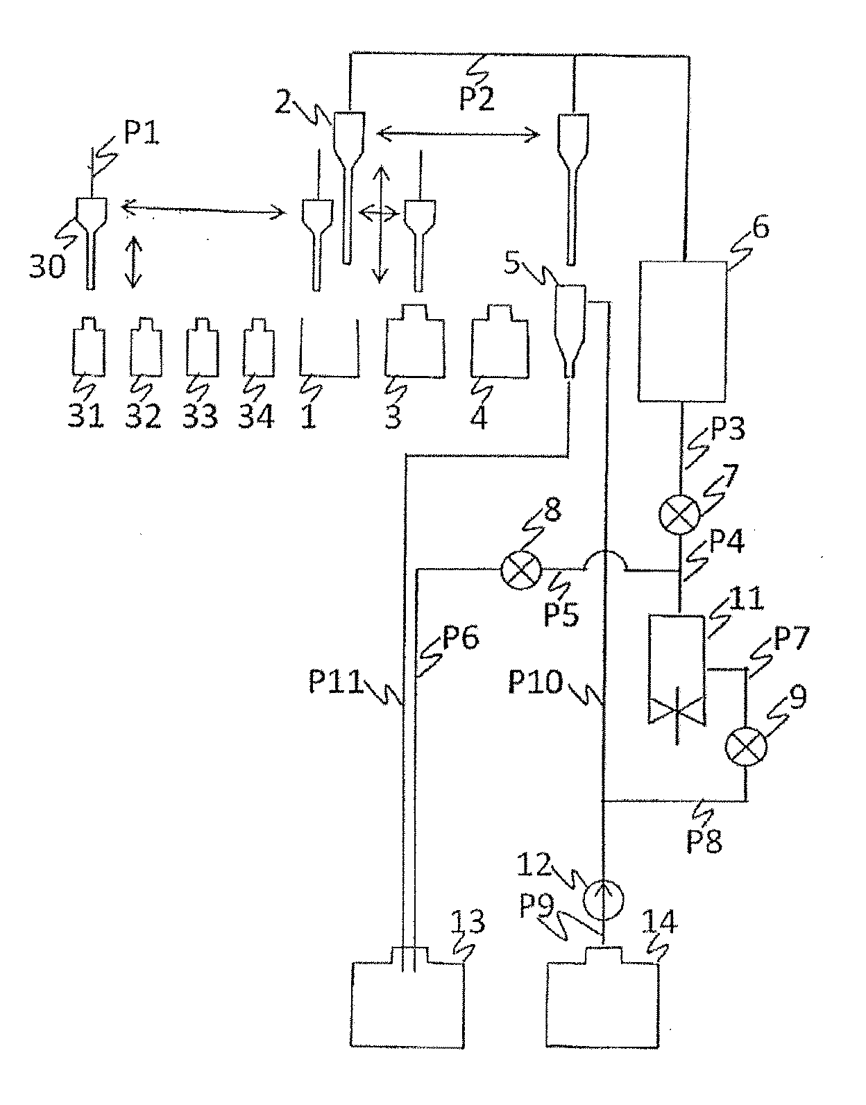
[0047]Hereinafter, a method and an device for immunity analysis according to an embodiment of the present invention will be described using FIG. 1 to FIG. 4. First, a system configuration of an analyzing device of the present embodiment will be described using FIG. 1.

[0048]In FIG. 1, the analyzing device of the present embodiment is provided with a sample bottle 31 containing a sample, a beads bottle 32 containing a beads solution including magnetic particles, a first reagent bottle 33 containing a first reagent that binds magnetic particles to a specific component in the sample, a second reagent bottle 34 containing a second reagent that labels a labeling substance that generates luminescence through an electrochemical reaction and is bound to a specific component in the sample, a buffer solution bottle 3 containing a buffer solution including a substance that induces electrochemical luminescence of the labeling substance, a cleaning liquid bottle 4 containing a cleaning liquid, a ...

embodiment 2

[0081]FIG. 6 illustrates another embodiment of the present invention.

[0082]A flow-through cell configuration thereof is similar to that of the flow-through cell created in Embodiment 1 except the working electrode shape. A working electrode 15-3 is bifurcated in an exposed region where the working electrode in the flow chamber. The exposed region on the upstream side of the flow chamber is called an “upstream-side working electrode exposed region” and the exposed region on the downstream side is called a “downstream-side working electrode exposed region.”

[0083]The upstream-side working electrode exposed region includes upstream-side emarginated parts 94 at both ends on the upstream side thereof. On the other hand, the upstream-side working electrode exposed region includes a downstream-side emarginated part 95 on the downstream side thereof. A centroid 91-3 of the upstream-side working electrode exposed region is located in the upstream side from the centroid 92 of the top part of t...

embodiment 3

[0086]Another embodiment of the present invention will be described.

[0087]The present embodiment assumes that the working electrode has a shape similar to a conventional one. The light-receiving window 22 is partially covered to prevent luminescence generated from the downstream side of the trapping region from entering the photomultiplier tube. This prevents luminescence from regions where there are numerous noise components from entering the photomultiplier tube, leading to an improvement of the SN ratio. Moreover, covering the light-receiving window eliminates the necessity for fine processing / control of the electrode shape (may also be a shape identical to or simpler than that of the comparative example). Therefore, it is possible to reduce variations in electrochemical reaction efficiency originating from variations in the working accuracy of the electrode end or the like when working the electrode shape. That is, it is possible to improve the SN ratio without causing the accur...


PUM


Abstract

An analyzing device of the present invention is provided with a flow chamber that a fluid including magnetic particles associated with a labeling substance flows from a fluid inlet to a fluid outlet, magnetic trap means to apply a magnetic field for trapping the magnetic particles to the fluid in the flow chamber, a working electrode and a counter electrode to apply a voltage to the magnetic particles trapped by the magnetic trap means, and to emit a luminescence, a light detection element to detect a luminescence derived from the labeling substance on the magnetic particles trapped in the flow chamber, and regulating means to regulate a region that the light detection element detects the luminescence derived from the labeling substance on a part of magnetic particles of them trapped by the magnetic trap means.

Description

TECHNICAL FIELD[0001]The present invention relates to a device for immunity analysis (immunoassay) using a reaction between an antigen and an antibody, and more particularly, to an analyzing device using magnetic particles as a solid phase for immunity reaction.BACKGROUND ART[0002]An immunity reaction is used to form an immunity complex for identifying an antibody or antigen in a biological sample such as serum or urine. When a solid phase and a liquid phase are made to react with each other, it is a general practice that a labeled antibody is used as a reagent and the liquid phase is measured using a detection element after the reaction. Radioisotopes, enzymes, colored particles, fluorescent substances, light-emitting (luminescent) substances or the like are known as the labeling substances.[0003]In electrochemical luminescent flow-through cells according to prior arts, an excessive amount of luminescent reagent is added with respect to an amount of a measuring target in order to c...

Claims


Application Information

Patent Timeline
IPC IPC(8): G01N33/561
CPCG01N21/76G01N21/05G01N21/69G01N33/561G01N27/745G01N35/0098G01N33/54326
Inventor NOBUKI, SHUNICHIROMAESHIMA, MUNEOTAMURA, TERUMIIMAI, KENTA
Owner ROCHE DIAGNOSTICS OPERATIONS
Why Eureka
Try Eureka