Method and device for laser marking with grey level calibration

a laser marking and calibration technology, applied in laser beam welding apparatus, printing, printing processes, etc., can solve the problems of only being performed by specially trained technicians, requiring sophisticated optical measuring devices, and only being able to accurately specify laser output or laser pulse energy accurately, so as to achieve reliable determination of deposited radiation output and save time

Active Publication Date: 2016-03-10
BUNDESDRUCKEREI GMBH
View PDF3 Cites 4 Cited by
  • Summary
  • Abstract
  • Description
  • Claims
  • Application Information

AI Technical Summary

Benefits of technology

[0025]The advantage of the invention is that a calibration of the device for laser marking can be performed without this requiring a specially trained person. This is of particular advantage especially for decentrally used laser marking devices. If the control unit of the device is designed such that it can receive an assignment function or one of different assignment functions can be selected for different marking operations, then it is further possible to mark different document blanks with one and the same device and to perform calibrations for this. This is especially advantageous if novel document blanks are to be used, for which it is only required to provide an assignment function adapted to the document blank, in order to mark any grey scale graphics in the document blank with consistent grey scale graphics each having absolute grey values. Adapted to the special document blank or a marking plane selected therefor, only the corresponding assignment function must be provided, received and / or selected in order to enable reliable marking.
[0026]In a preferred embodiment of the invention, it is intended that the measuring head measuring absolutely comprises a thermopile. A thermopile consists of a thermocouple or of several thermocouples thermally connected in parallel and electrically connected in series, wherein always one connection point of the thermocouple is subjected to radiation and the other one is protected from the radiation. With a once-calibrated thermopile, a deposited radiation output can be determined reliably and absolutely. Such accuracy cannot, for example, be achieved by means of photodiodes or other currently known semiconductor components since their measurement values, in particular, heavily depend on the ambient conditions, and vary.
[0027]A preferred method thus envisages that an output of the laser light is measured by means of a measuring head comprising a thermopile.
[0028]The minimal fluctuations, which may occur during a marking operation, of the actually generated laser output or laser pulse energy for the different laser control signal values, which occur during a marking operation, it is intended in an embodiment of the invention that, additionally, there is a further output measuring device or laser pulse energy measuring device which performs a relative output or laser pulse energy measurement. It is preferably formed by means of a semiconductor component, especially a light-sensitive diode. The captured relative output fluctuations or pulse energy fluctuations can be used analogously to the ascertained absolute output values / pulse energy values in order to effect, between two calibration steps for certain brightness values, a short-term adaptation of the assignment function.
[0029]In a preferred embodiment of the invention, it is thus intended that, after marking a predefined number of security documents, a calibration step for at least one brightness value is performed. In an embodiment of the invention, between the marking of two security documents, a calibration step for only one brightness value is performed. In another embodiment, it is intended that successive calibration steps are performed for different brightness values, provided that no adaptation of the calibration is necessary. It is understood that, at the beginning of a commissioning of a laser marking device, a calibration each shall be performed for all desired brightness values. In continuous operation, however, only individual calibration steps are then necessary for individual brightness values in order to check the calibration and to save time. If time is not a limiting factor, the full calibration should always be performed.
[0030]Usually, after performing of a calibration step for a brightness value, in which a change of the assignment function was performed, a required change of the assignment function for other brightness values can be extrapolated. If such an extrapolation is performed, then, when performing a subsequent calibration step for one of these other brightness values, it is possible to achieve that the calibration step necessitates no further change of the assignment function. If the calibration is performed such that, for each brightness value for which a calibration is performed, calibration steps are performed until adaptation of the assignment function in the context of a specified tolerance is no longer necessary, then such an extrapolation often leads to a clear acceleration of a calibration, in which several brightness values calibrated as soon as an adaptation of the assignment function was necessary for a brightness value. During the calibration on the occasion of the commissioning, too, an extrapolation leads to an acceleration of the entire calibration.

Problems solved by technology

However, the laser output or laser pulse energy can only be influenced relatively by such a laser control signal.
This means that an accurate laser output or laser pulse energy cannot be accurately specified.
These calibrations can only be performed by specially trained technicians and / or require sophisticated optical measuring devices which can accurately compare the grey scale values to each other.

Method used


Image

  • Method and device for laser marking with grey level calibration
  • Method and device for laser marking with grey level calibration
  • Method and device for laser marking with grey level calibration

Examples


Embodiment Construction

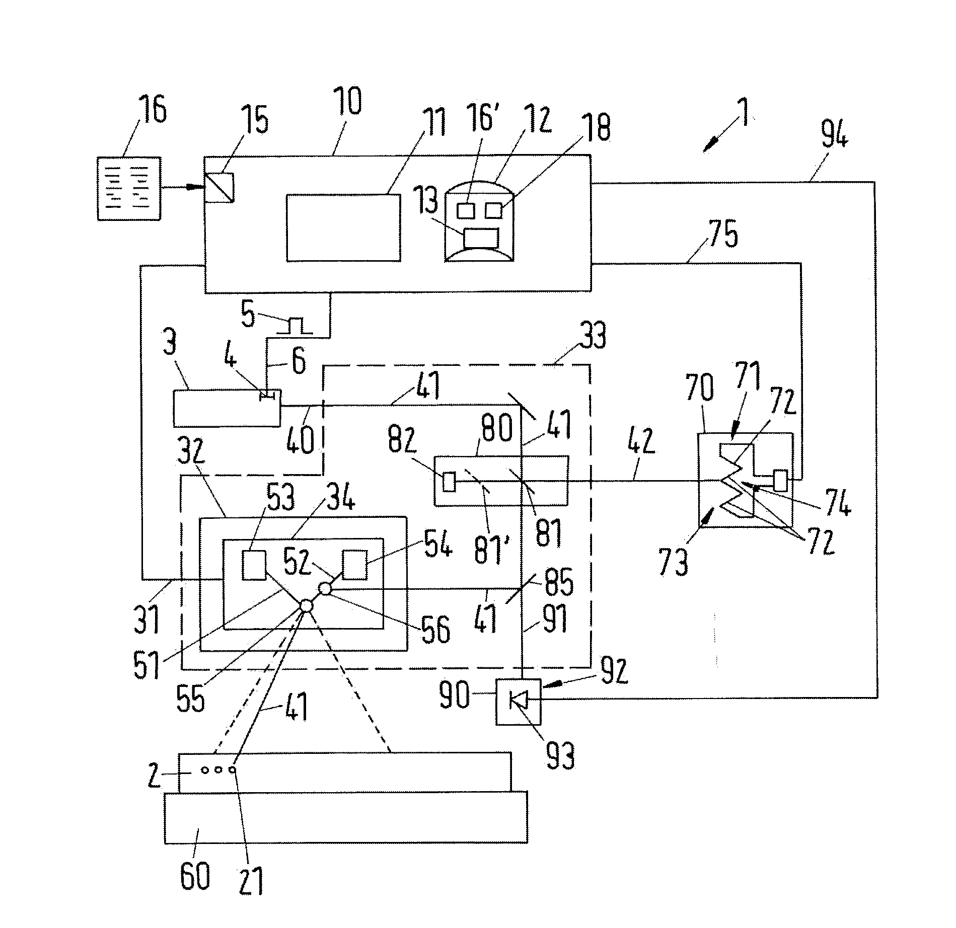
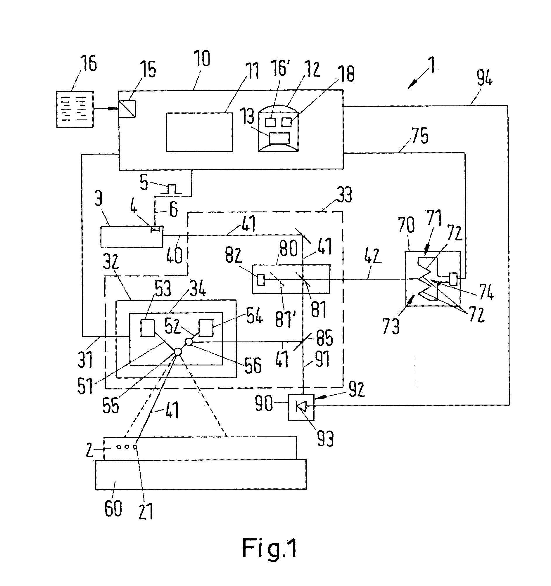
[0009]A method for laser marking security documents is created, comprising the following steps:

[0010]a) capturing graphic information which describes a graphic having different brightness values;

[0011]b) generating a position control signal and a laser control signal dependent on the graphic information, wherein each brightness value is assigned a nominal laser light output or nominal laser pulse energy which is needed to induce a laser marking with the corresponding brightness value in a security document and, when generating the laser control signal by means of an assignment function, each brightness value is assigned a control value which is provided for generating laser light with the corresponding laser light output or laser pulse energy,

[0012]c) controlling a laser by means of the laser control signal and emitting laser light with a laser light output or a laser pulse energy according to the laser control signal; and

[0013]d) temporally adapted controlling of at least one posit...


PUM

PropertyMeasurementUnit
repetition frequencyaaaaaaaaaa
brightnessaaaaaaaaaa

Abstract

The invention provides a method and a device which enable laser markings to be performed and reduce the need of intervention by a service technician and still enable accurate grey scale markings to be performed reliably. Embodiments of the invention relate to a method and a device such that the device for laser marking is equipped with a measuring head which measures a laser output or laser pulse energy absolutely and using a measurement result thus obtained in order to change and suitably adapt an assignment function which assigns laser control values to grey scale values.

Description

BACKGROUND OF THE INVENTION[0001]1. Field of the Invention[0002]The invention relates to a method for laser marking security documents and a corresponding device which enable the storage of graphic information, which describes a graphic having different brightness values, in a security document.[0003]2. Brief Description of the Related Art[0004]From prior art, it is known to mark security documents using laser radiation. In particular security documents, which are produced based on plastics, can be marked by means of laser radiation such that graphic information is stored on the surface of or inside the security document. To achieve storage inside a security document, pigments are for example added to a transparent material layer, which indeed promote absorption of laser radiation but do not at all or only insignificantly impair a general transparency of the material. The laser irradiation is absorbed locally in the layer provided with the pigments and this, for example, causes a ca...

Claims


Application Information

Patent Timeline
Patent Type & Authority Applications(United States)
IPC IPC(8): B41M3/14B23K26/03B23K26/064B23K26/08B23K26/362B23K26/70
CPCB41M3/14B23K26/362B23K26/064B23K26/702B23K26/08B23K26/03B41M5/26B23K26/361
Inventor RICHTER, WERNER
Owner BUNDESDRUCKEREI GMBH
Why Eureka
Try Eureka