
Compact Energy Cycle Construction Utilizing Some Combination of a Scroll Type Expander, Pump, and Compressor for Operating According to a Rankine, an Organic Rankine, Heat Pump, or Combined Orgainc Rankine and Heat Pump Cycle

a technology of energy cycle and scroll expansion, which is applied in the direction of heat pump, liquid fuel engine, lighting and heating apparatus, etc., can solve the problems of largely unsatisfactory desire, and achieve the effects of more compact energy cycle construction, less cost, and reliable energy cycle construction

Active Publication Date: 2016-03-10
AIR SQUARED
View PDF12 Cites 3 Cited by
  • Summary
  • Abstract
  • Description
  • Claims
  • Application Information

AI Technical Summary

Benefits of technology

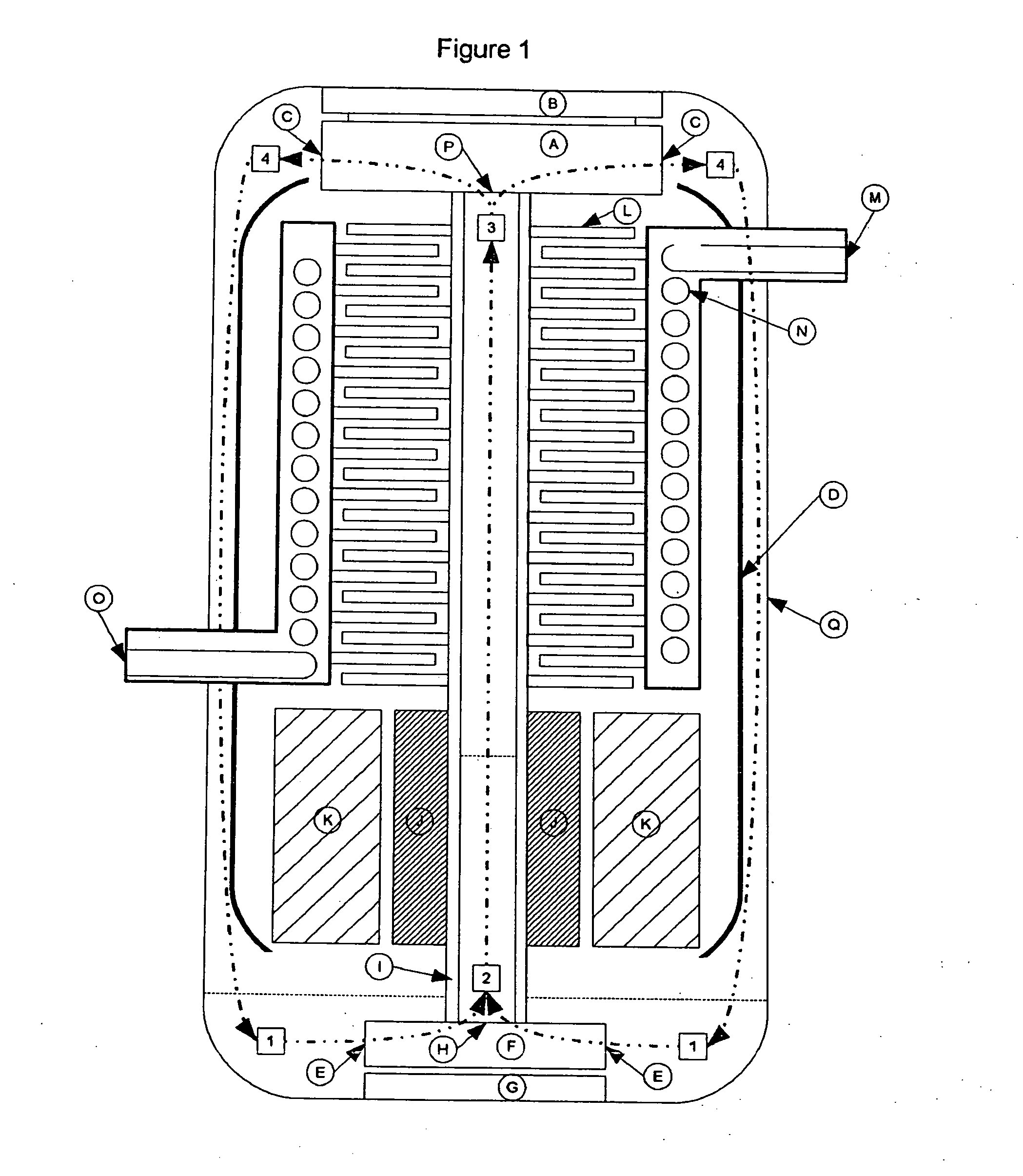
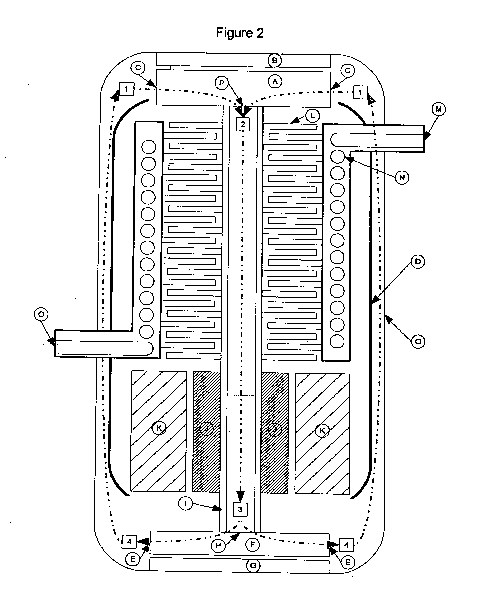
[0009]This invention has thus been developed to result in a more compact, lower cost, and more reliable energy cycle construction. The resulting construction integrates system components into a closed, preferably cylindrical, container housing, sometimes hereinafter referred to more simply as the container, within which container housing the working fluid flows about a torus in the poloidal direction. The rotary working fluid treatment devices utilize a scroll type design and rotate about a common shaft, with the evaporation and condensing processes being affected while the fluid is in transit between the rotary fluid treatment devices. This type of system design can be advantageously used for power generation through the use of a Rankine Cycle or ORC, or can be used for heat pumping through the use of a Refrigeration / Heat Pump Cycle, sometimes hereinafter referred to more simply as a Heat Pump Cycle or a Refrigeration Cycle.
[0017]The present invention may thus be encompassed within and practiced by various constructions that incorporate all the rotary components within a single container housing, including systems such as the three (3) unique, preferred constructions noted hereinabove. Such design decreases the risk of refrigerant leakage, reduces overall system cost, due to the integration of components, and simplifies the energy cycle, which increases reliability, by eliminating all piping between components.
[0018]In addition, the unique design of such systems increases system efficiency and decreases system complexity, including by placing all the rotating equipment on a single shaft. For a refrigeration / heat pump cycle the design increases efficiency by replacing an expansion valve with an expander to recover power in the expansion process.

Problems solved by technology

To this point in time, however, that desire has remained largely unsatisfied.

Method used


Image

  • Compact Energy Cycle Construction Utilizing Some Combination of a Scroll Type Expander, Pump, and Compressor for Operating According to a Rankine, an Organic Rankine, Heat Pump, or Combined Orgainc Rankine and Heat Pump Cycle
  • Compact Energy Cycle Construction Utilizing Some Combination of a Scroll Type Expander, Pump, and Compressor for Operating According to a Rankine, an Organic Rankine, Heat Pump, or Combined Orgainc Rankine and Heat Pump Cycle
  • Compact Energy Cycle Construction Utilizing Some Combination of a Scroll Type Expander, Pump, and Compressor for Operating According to a Rankine, an Organic Rankine, Heat Pump, or Combined Orgainc Rankine and Heat Pump Cycle

Examples


Embodiment Construction

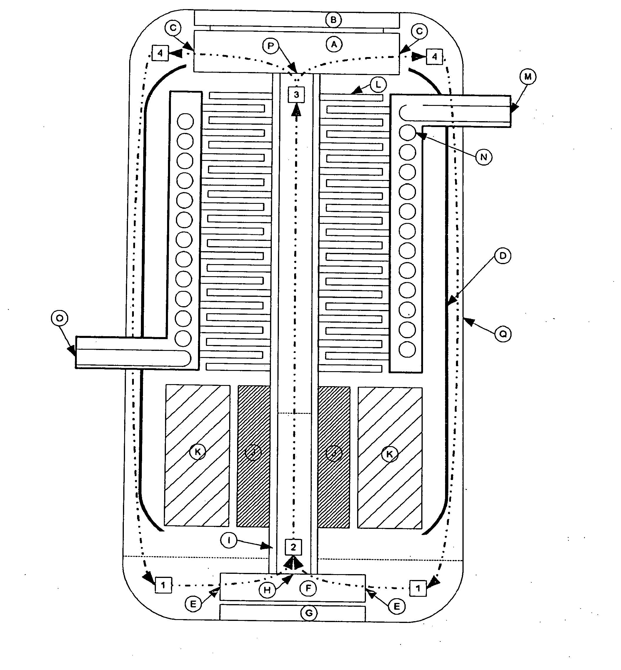
[0026]With reference now to the drawings, where like identification symbols in any given figure refer to like items, but where such identification symbols may vary from figure to figure, FIG. 1 depicts an embodiment according to the present invention, operating as or in accordance with a Rankine Cycle or Organic Rankine Cycle, with components and features of such embodiment having the identification symbols as set forth in the following Table 1:

TABLE 1FIG. 1 IdentifiersIdentifierItem DescriptionComponents (Alphabetized circles)AOrbiting portion of the orbital scroll expander, or drivingportion of a co-rotating scroll expanderBFixed portion of the orbital scroll expander, or drivenportion of a co-rotating scroll expanderCScroll expander OutletDInsulation / sealing between condenser and rotatingequipmentEScroll pump inletFDriving portion of a co-rotating scroll pumpGDriven portion of a co-rotating scroll pumpHScroll pump outletIHollow rotating shaft connecting pump to expanderJGenerator...


PUM


Abstract

A compact energy cycle construction that operates as or in accordance with a Rankine, Organic Rankine, Heat Pump, or Combined Organic Rankine and Heat Pump Cycle, comprising a compact housing of a generally cylindrical form with some combination of a scroll type expander, pump, and compressor disposed therein to share a common shaft with a motor or generator and to form an integrated system, with the working fluid of the system circulating within the housing as a torus along the common shaft and toroidally within the housing as the system operates.

Description

CROSS REFERENCE TO RELATED APPLICATIONS[0001]This continuation patent application claims priority to the patent application having Ser. No. 13 / 986,349, filed on Apr. 23, 2013, which claims priority to the provisional patent application having Ser. No. 61 / 687,464, filed on Apr. 25, 2012, which claims priority as a continuation-in-part patent application to the patent application having Ser. No. 13 / 507,779, filed on Jul. 30, 2012, now Publication No. US 2013-0036762 A1, which claims priority to the provisional patent application having Ser. No. 61 / 574,771, filed Aug. 9, 2011, now expired.FIELD OF THE INVENTION[0002]The present invention is directed to an energy cycle construction, several rotating components of which are integrated within a compact container housing to share a common shaft along which working fluid transits as the construction operates.[0003]The container housing is preferably of a generally cylindrical configuration with some combination of a scroll type expander, pu...

Claims


Application Information

Patent Timeline
Patent Type & Authority Applications(United States)
IPC IPC(8): F01K13/02F01C1/02F04C18/02F25B30/02
CPCF01K13/02F25B30/02F01C1/0215F04C18/0215F01C1/0269F01C11/006F01K9/02F01K11/00F01K11/04F04C18/0269F04C23/008F04C29/023F04C29/042F25B1/04F25B11/04F01K13/00F25B3/00
Inventor SHAFFER, ROBERT W.SHAFFER, BRYCE R.
Owner AIR SQUARED
Learn More