A lighting device and luminaire comprising an antenna

a technology of lighting devices and luminaires, which is applied in the direction of resonant antennas, semiconductor devices for light sources, lighting and heating apparatus, etc., can solve the problems of practicability and feasible ways, and achieve the effect of improving the directivity of the antenna and improving the performance of the second radiator

Active Publication Date: 2016-03-10
SIGNIFY HLDG BV
View PDF6 Cites 20 Cited by
  • Summary
  • Abstract
  • Description
  • Claims
  • Application Information

AI Technical Summary

Benefits of technology

[0006]It is an object of the invention to provide a lighting device having RF communication in which the light emission power may be increased.
[0029]In a further embodiment, the lighting device comprises dielectric material between the primary radiator and the back plane. Also the material within the cavity will influence the resonant length of the slot. A higher dielectric medium reduces the resonant length of slot, allowing for a smaller antenna. The tradeoff is that the bandwidth and efficiency typically decrease with a dielectric cavity medium.

Problems solved by technology

But this prior art only propose such possibility without giving any practical and feasible way of implementing the antennas on a heat sink.

Method used


Image

  • A lighting device and luminaire comprising an antenna
  • A lighting device and luminaire comprising an antenna
  • A lighting device and luminaire comprising an antenna

Examples


first embodiment

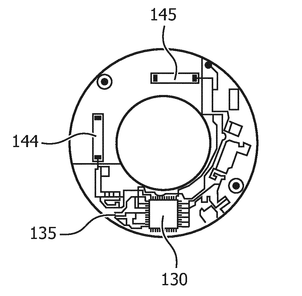
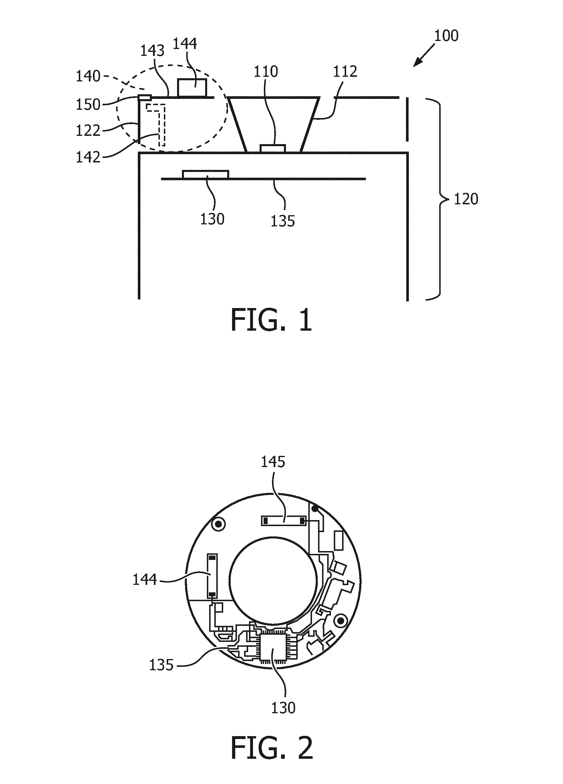
[0054]FIG. 1 shows a schematic cross-sectional view of the lighting device 100 according to the invention. This first lighting device comprises a light emitter 110 thermally connected to a heat sink 120 and comprises a communication circuit 130 arranged on a Printed Circuit Board (further also indicated as PCB) 135 for transmitting and / or receiving a communication signal. The heat sink 120 comprises a first conductive part 122 which comprises a first chip antenna 144 which is a first mono-pole antenna 144. Such first chip antenna 144 may be a commercially available chip antenna, often available as Surface Mount Devices (further also indicated as SMD) which can be mounted on a Printed Circuit Board (further also indicated as PCB). Alternatively, the first mono-pole antenna 144 may, for example, be a copper trace with predefined dimensions, printed on a PCB. The first conductive part 122 must be electrically conductive and may for example be made partially or wholly from metal or any ...

second embodiment

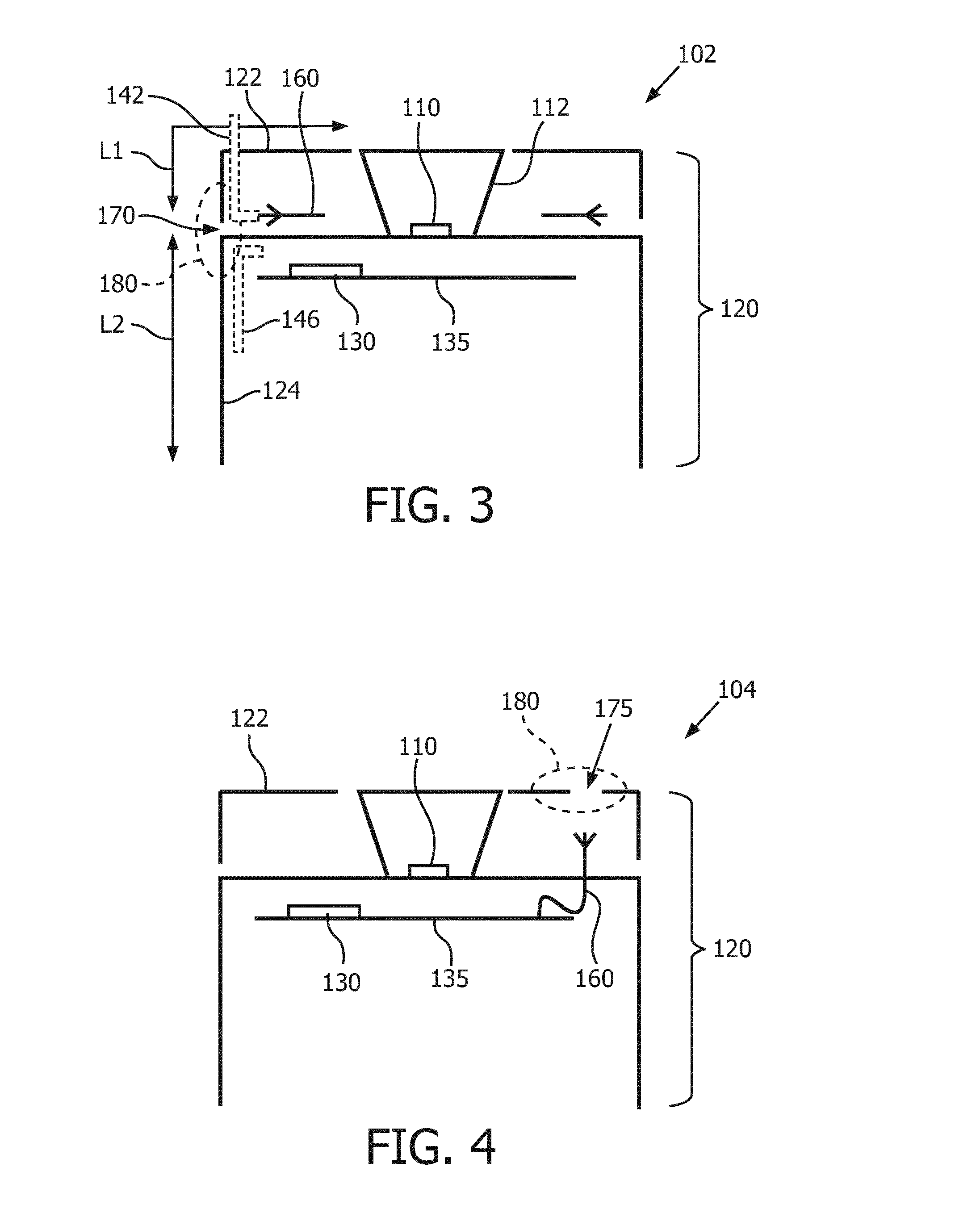
[0059]FIG. 3 shows a schematic cross-sectional view of the lighting device 102 according to the invention. The lighting device 102 shown in FIG. 3 also comprises the light emitter 110, heat sink 120, PCB 135 and communication circuit 130, similar as the embodiment shown in FIG. 1. Also the optional collimator 112 is shown in FIG. 3. The lighting device 102 in FIG. 3 further comprises a primary radiator 160 (two are drawn in FIG. 3, but only one has a label 160) arranged inside the heat sink 120 and configured for activating the first conductive part 122 around a gap 170 between the first conductive part 122 and the remainder of the heat sink 120. The primary radiator 160 typically is a dipole antenna 160 and the electro-magnetic signal emitted by the primary radiator 160 induces currents flowing around the gap 170 and as such activates the first conductive part 122 around the gap 170 which subsequently starts to emit a similar communication signal. So the primary radiator 160 activa...

third embodiment

[0062]FIG. 4 shows a schematic cross-sectional view of the lighting device 104 according to the invention. Also in the embodiment shown in FIG. 4, the light emitter 110, heat sink 120, PCB 135 and communication circuit 130 are shown, similar as the embodiment of FIG. 1. However, now, the gap in the first conductive part 122 comprises a slot 175 being an opening completely surrounded by the first conductive part 122. This slot 175 is the secondary radiator 180 (again indicated with a dotted oval) which has a resonance frequency including the signal frequency of the communication signal. The slot 175 acts as the dipole antenna 140 which may, for example, be activated by the primary radiator 160 such as the primary antenna 160 inside the heat sink 120. Again, the electro-magnetic signal emitted by the primary antenna 160 induces currents flowing around the slot 175 and as such activates the first conductive part 122 around the slot 175 which subsequently starts to emit a similar commun...


PUM


Abstract

The invention provides a lighting device (104) and a luminaire (200). The lighting device comprises a light emitter (110) thermally connected to a heat sink (120). The lighting device further comprises a communication circuit (130) coupled to the heat sink for transmitting and / or receiving a communication signal. A first conductive part (122) of the heat sink comprises at least a first pole (142) of a dipole antenna (140) for transmitting and / or receiving the communication signal via the heat sink. This first pole of the dipole antenna may be induced via a primary radiator (160) to activate the gap (170).

Description

FIELD OF THE INVENTION[0001]The invention relates to lighting device comprising an antenna. The invention further relates to a luminaire comprising the lighting device.BACKGROUND OF THE INVENTION[0002]Tele-management of light sources both for indoor and outdoor applications are increasingly popular. Intelligent lighting has become widespread, and RF communication is a powerful technology to be used in this tele-management of lamps, in particular for domestic and office environments. Instead of controlling the power supply to the lamp, the trend has moved towards directly controlling the light source or lighting device (for example an exchangeable element of the lamp) by sending an RF control signal to the lighting device.[0003]One example of such light source comprising a luminescent material can be found in the published patent application US2012 / 0274208A1 which relates to a lighting device such as a replacement lighting device, comprising a light source (e.g. LED) for producing li...

Claims


Application Information

Patent Timeline
Patent Type & Authority Applications(United States)
IPC IPC(8): H01Q1/24F21V23/04F21V29/70H01Q1/02H01Q9/16H01Q21/00
CPCH01Q1/24H01Q1/02F21V23/045H01Q21/00F21V29/70H01Q9/16H01Q1/44H01Q9/38H01Q13/16F21K9/232
Inventor VAN DIJK, NICOCREEMERS, HENRICUS MATHIJS MARIAVAN DER MERWE, JACOBANERJEE, KONIKAVAN KAATHOVEN, DIRK JANDE JONG, LAMBERTUS ADRIANUS MARINUSDENKER, ROGER HENRILOUH, YACOUBAGEELS, MARIJN
Owner SIGNIFY HLDG BV
Why Eureka
Try Eureka