Wireless transmission of high quality video

a high-quality, still-and-video technology, applied in the field of wireless transmission of high-quality still-and-video images, can solve the problems of complex hardware for implementing compression, inapplicability to home appliances, and general undesired connection of screen to set-top box through cable, so as to achieve simple compression hardware, improve compression results, and simplify the compression procedure

Inactive Publication Date: 2016-03-10
AMIMON
View PDF2 Cites 5 Cited by
  • Summary
  • Abstract
  • Description
  • Claims
  • Application Information

AI Technical Summary

Benefits of technology

[0015]An aspect of some embodiments of the invention relates to transmission of high definition video compressed in an image domain, i.e., the compression does not involve a transform to a different domain (e.g., using DCT, wavelet or Fourier transforms). In some embodiments of the invention, in the image domain, the image is represented by color values of pixels. Optionally, the compression does not directly link more than a small vicinity of pixels (e.g., having a diameter of up to 20 pixels, or even 10 pixels) together, such that errors in a given pixel do not propagate at all or the errors fade as they propagate. In some embodiments of the invention, at least some of the pixels are encoded without relation to other pixels. These pixels are optionally used as a base for encoding other pixels, such that the effect of an error in one pixel fades quickly. Not using a transform in the compression may simplify the compression and make the compression cheaper.
[0016]Alternatively or additionally, the compression does not link between pixels of different frames. Using an image domain compression, although requiring a relatively large bandwidth for transmission is more efficient, since it is less susceptible to noise and fading.

Problems solved by technology

Connection of the screen to the set-top box through cables is generally undesired for aesthetic reasons and / or installation convenience and wireless transmission of the video signals from the set-top box to the screen is preferred.
Known strong video compression methods (e.g., having a compression factor of above 1:30) require very complex hardware for implementing the compression, which is not practical for home apparatus.
Alternatively or additionally, strong video compression methods have a relatively high image degradation, which is unacceptable for high quality video display.
The known strong video compression methods also suffer from high sensitivity to transient noise and fading, such that an entire frame or even more may be lost due to a short fading period.
One reason that this is not implemented is that the content providers do not want to provide the decryption keys to producers of the wireless transmission equipment.
Known high rate and high quality video compression methods, on the other hand, do not sufficiently compress the video signals to allow their practical transmission on the available bandwidth with an acceptable safety margin protection from noise and fading.
Using a small safety margin requires a retransmission mechanism with a large buffer, which also increases the cost of the transmission apparatus.
This method does not substantially save bandwidth, but rather allows adaptation to available cable bandwidth.
In addition, this method allows viewing low quality images when the noise level is relatively high.
However, in a wireless environment, the proportion of time in which low quality images would be displayed is unacceptable.

Method used


Image

  • Wireless transmission of high quality video
  • Wireless transmission of high quality video
  • Wireless transmission of high quality video

Examples


Embodiment Construction

System Overview

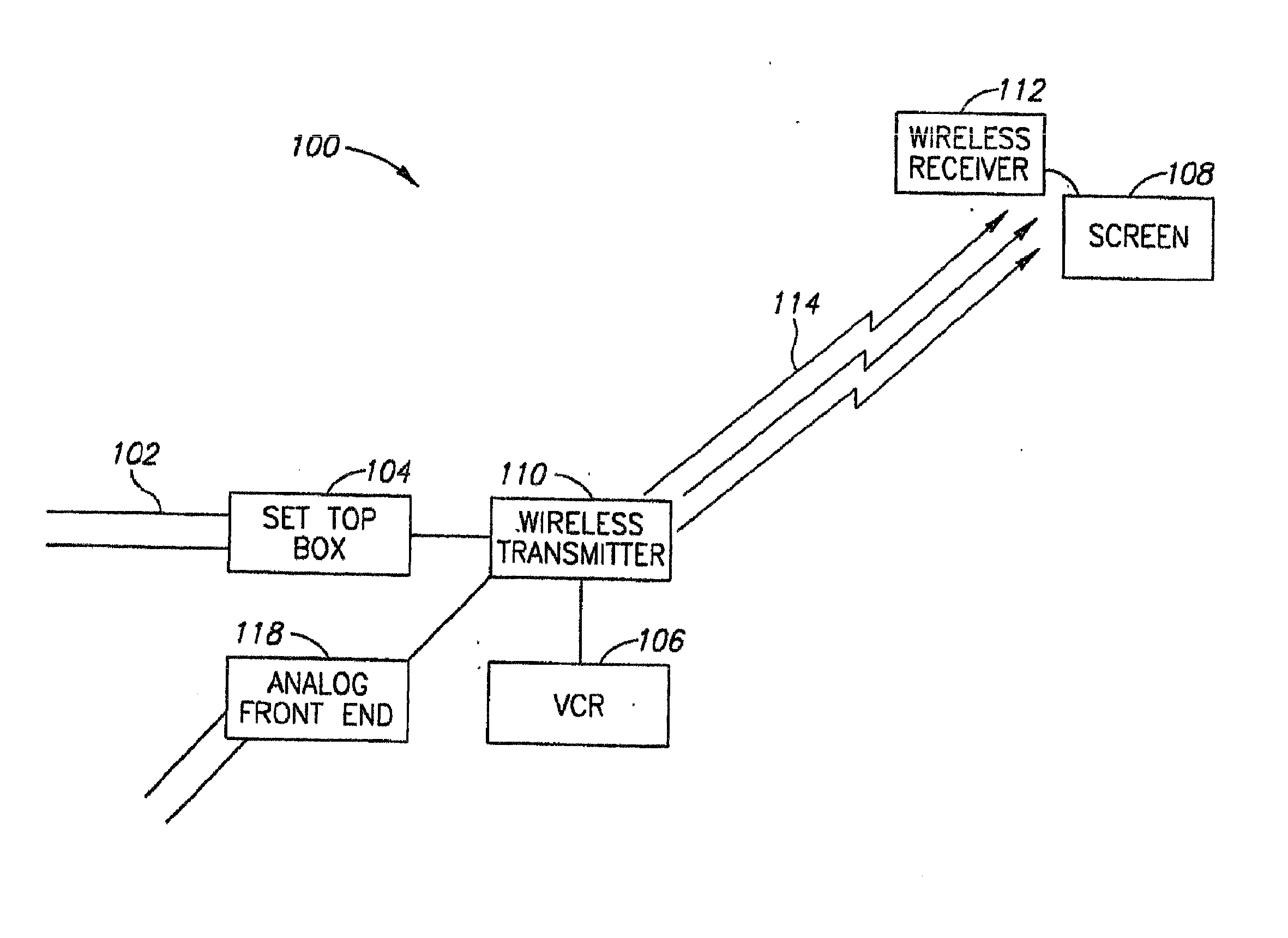
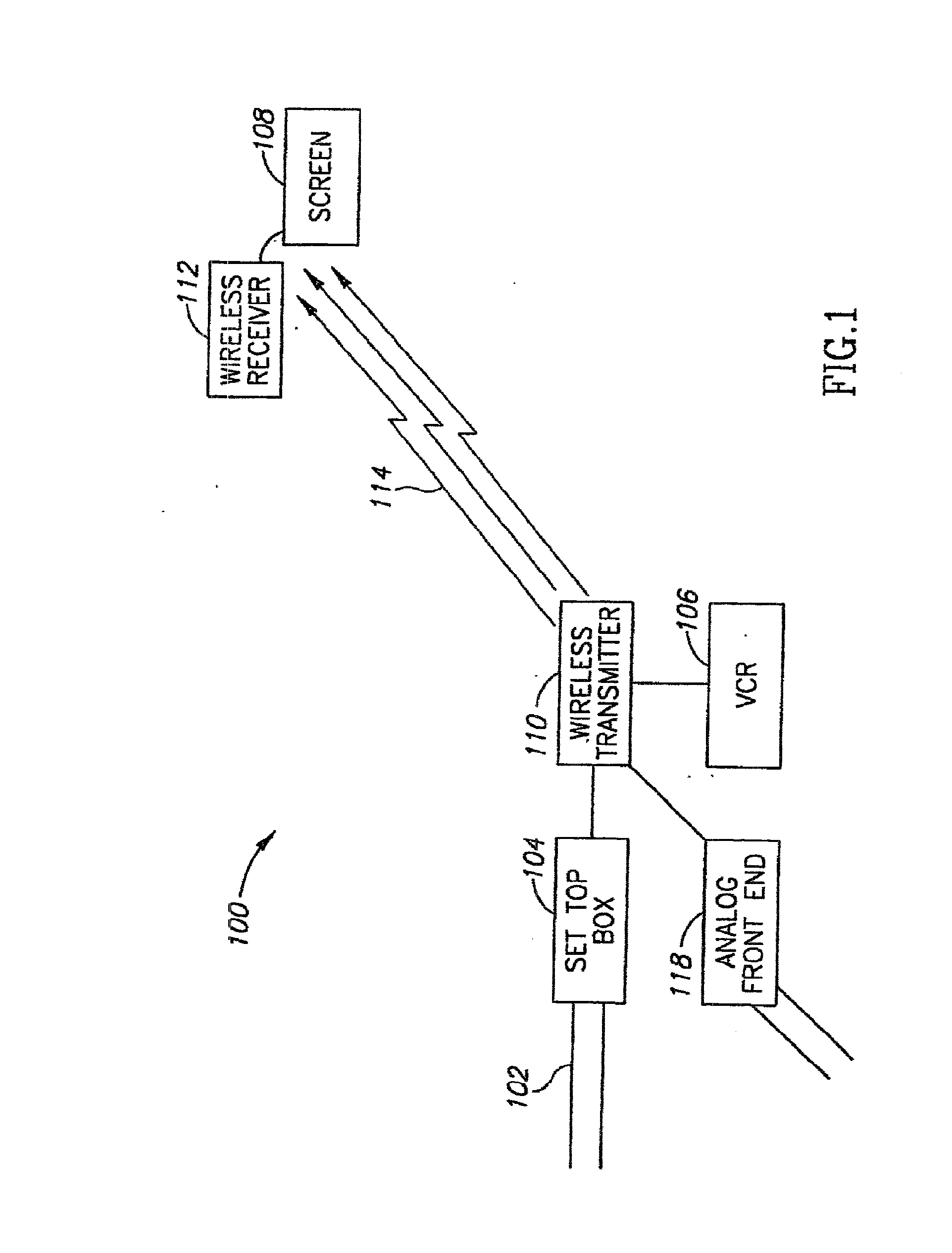
[0094]FIG. 1 is a schematic illustration of a wireless transmission system 100, in accordance with an exemplary embodiment of the invention. System 100 comprises a wireless transceiver 110 which receives video signals from a set-top box 104, a VCR 106, a game box, a DVD and / or any other video signal source, for example through an analog front end 118. The video signals are compressed and encoded by wireless transmitter 110 and transmitted on a wireless link 114 to a wireless receiver 112. Wireless receiver 112 decompresses and decodes the signals for display on a screen 108.

[0095]Set-top box 104 optionally receives the video signals in a standard format, such as HDTV or SDTV, from a video source, over cables 102. In some embodiments of the invention, the video signals received through cables 102 are encrypted and compressed by the video source and are decompressed and decrypted by set-top box 104. Wireless transmitter 110 generally receives the video signals after dec...


PUM


Abstract

A method of transmitting video images. The method includes providing a high definition video stream, compressing the video stream using an image domain compression method, in which each pixel is coded based on a vicinity of the pixel and transmitting the compressed video stream over a fading transmission channel.

Description

CROSS-REFERENCE TO RELATED APPLICATIONS[0001]This application is a continuation application claiming benefit from U.S. patent application Ser. No. 10 / 574,023, filed Mar. 23, 2006, which is hereby incorporated in its entirety by reference.FIELD OF THE INVENTION[0002]The present invention relates generally to wireless transmission of high quality still and / or video images and particularly to high quality wireless transmission of images in relatively noisy and / or fading environments.BACKGROUND OF THE INVENTION[0003]In many houses, television and / or video signals are received through cable or satellite links at a set-top box at a fixed point in the house. In many cases it is desired to place a screen at a point distanced from the set-top box by a few meters. Connection of the screen to the set-top box through cables is generally undesired for aesthetic reasons and / or installation convenience and wireless transmission of the video signals from the set-top box to the screen is preferred. ...

Claims


Application Information

Patent Timeline
Patent Type & Authority Applications(United States)
IPC IPC(8): H04N19/40H04HH04J99/00H04N7/167H04N7/18H04N7/24H04N19/59H04N19/625
CPCH04N19/40H04N19/625H04N19/59H04B7/0669H04B7/08H04L27/2604H04L27/3488H04N7/1675H04N21/234327H04N21/23476H04N21/2383H04N21/2385H04N21/4382H04N21/44055H04N21/631
Inventor REZNIC, ZVIGERI, NOAM
Owner AMIMON
Why Eureka
Try Eureka