Bending control mechanism for endoscope

a control mechanism and endoscope technology, applied in gearing, medical science, diagnostics, etc., can solve the problems of increasing manufacturing costs, reducing productivity, and wire breaking, and achieves reduced bending operational force, improved operability, and simple structure

Inactive Publication Date: 2016-03-17
HOYA CORP
View PDF9 Cites 9 Cited by
  • Summary
  • Abstract
  • Description
  • Claims
  • Application Information

AI Technical Summary

Benefits of technology

[0008]The present invention has been devised in view of the above-mentioned problems and provides a bending control mechanism of an endoscope having a simple structure while achieving a decreased amount of bending-operational force, thereby exhibiting a superior operability.

Problems solved by technology

If the diameter of the pulley is reduced, although the amount of bending-operational force for winding the wire onto the pulley can be reduced, due to the wire which is wound onto the pulley being repeatedly extended and bent at a small radius of curvature, problems occur with fatigue occurring in the wire, thereby causing the wire to break.
Both of the inventions disclosed in Patent Literature 1 and 2 contribute to the reduction of the amount of bending-operational force; however, by adding links or a power-assisted motor, the component configuration becomes complex, thereby increasing manufacturing costs and risking a reduction in productivity.
Furthermore, as a result of adding such in-built components, the control body becomes larger and heavier, possibly deteriorating the holdability of the control body.
Furthermore, in the configuration disclosed in Patent Literature 1, due to the diameter of the pulley being reduced in size, the rotational angle of the pulley increases per unit amount of winding of the wire, and hence, the operational movement amount of the bending-control member becomes greater, thereby increasing the possibility of the person who is operating the endoscope getting a tired hand.

Method used


Image

  • Bending control mechanism for endoscope
  • Bending control mechanism for endoscope
  • Bending control mechanism for endoscope

Examples


Embodiment Construction

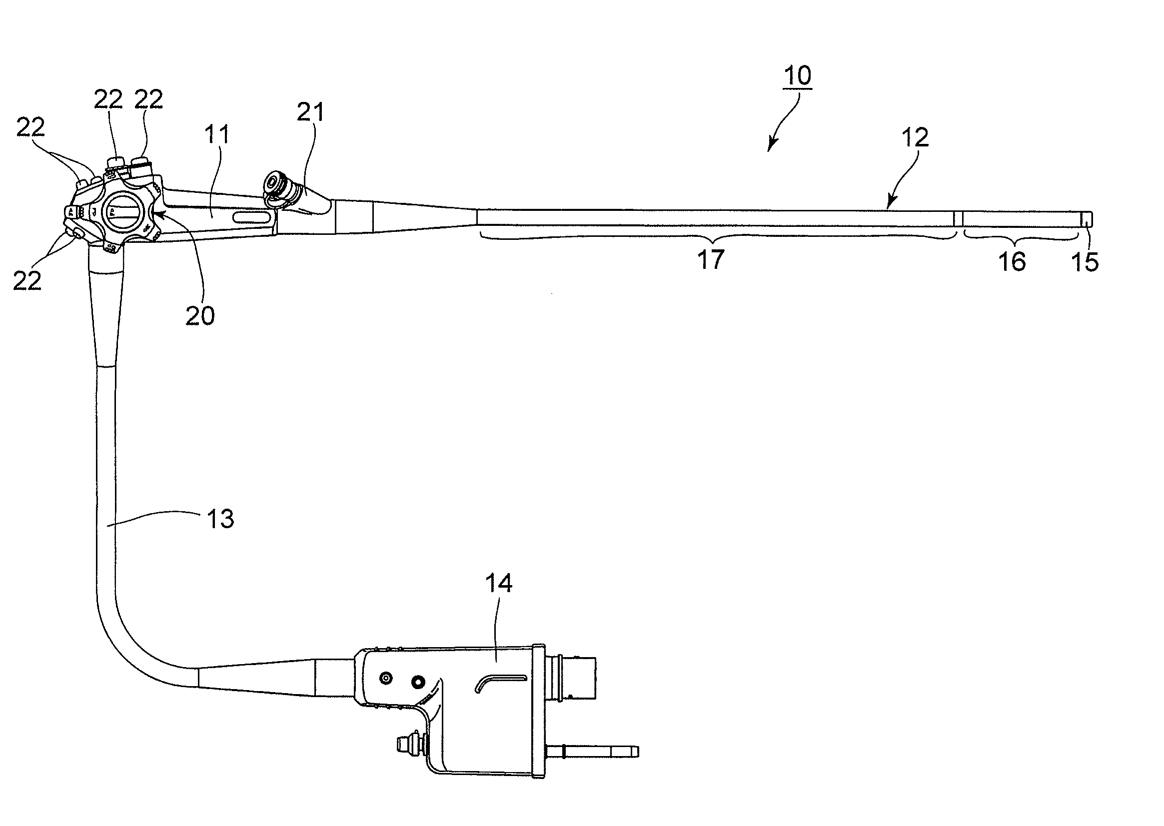
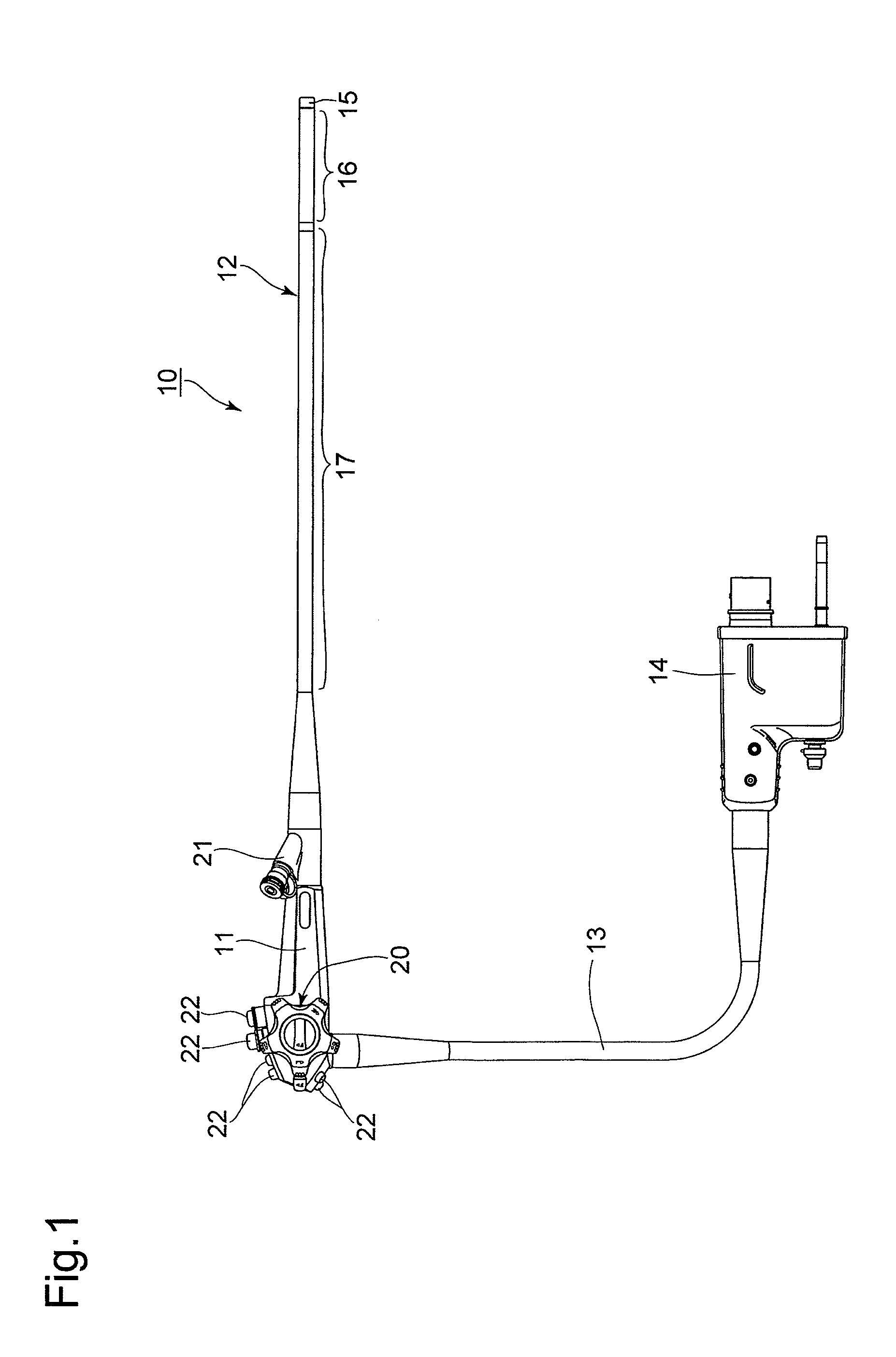
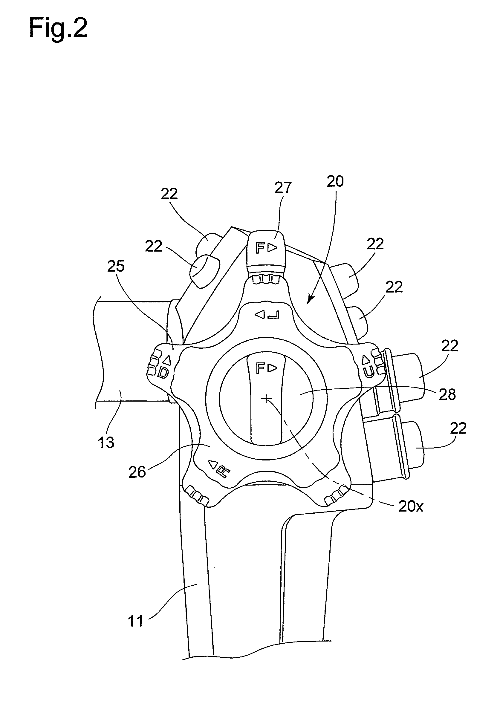
[0026]An endoscope 10 shown in FIG. 1 is provided with a control body 11, a small-diameter insertion section 12 which extends from the distal end of the control body 11, a universal cable 13 which extends from one side of the control body 11, and a connector 14 which is provided on an end of the universal cable 13. The connector 14 is connected to a processor, which is not shown in the drawings. The processor is provided with an in-built image processor and an in-built light-source lamp, for illumination purposes. The insertion section 12 is provided with a distal-end rigid section 15, a bendable section 16 which bends by being remotely controlled (operated) by the control body 11, and a flexible tube 17, in that order from the distal end of the insertion section 12. The control body 11 is provided with a bending controller 20 for controlling the bending of the bendable section 16, a treatment-tool insertion opening 21 via which a treatment tool such as a pair of forceps, etc., are ...


PUM


Abstract

A bending control mechanism for an endoscope, provided with a control body and a bendable section including an insertion section, the bending control mechanism includes a pulley which is rotatably provided in the control body, and a wire connected between the pulley and the bendable section. An outer peripheral profile of the pulley, onto which the wire is wound, includes a non-circular section including a small-radius section having a small radius from a rotational axis of the pulley, and a large-radius section having a radius from the rotational axis that is larger than the small radius. The wire is wound onto the large-radius section at an initial winding stage at which the bendable section is at a non-bending position. The wire is wound onto the small-radius section at a stage where the bendable section is bent by a maximum amount.

Description

BACKGROUND OF THE INVENTION[0001]1. Field of the Invention[0002]The present invention relates to a bending control mechanism of an endoscope.[0003]2. Description of the Related Art[0004]In an endoscope in which a bendable section that forms an insertion section can be controllably bent, a bending control mechanism, in which a bending control member is provided on a control body that connects onto a base end of the insertion section and by which the bending angle of the bendable section can be changed by pulling or loosening wires that are connected to a pulley by rotating the pulley by operating the bending control member, is heavily used (used very frequently). The pulling state of the wires is altered by increasing / decreasing the winding amount of the wires on the pulley in accordance with the rotation of the pulley. In such a type of bending control mechanism, since the resistance against a bending operation increases as the amount of bending of the bendable section increases, in...

Claims


Application Information

Patent Timeline
Patent Type & Authority Applications(United States)
IPC IPC(8): A61B1/005F16H19/06
CPCA61B1/0057A61B1/0052F16H19/06
Inventor SAITO, KEIICHI
Owner HOYA CORP
Why Eureka
Try Eureka