Supercharge Your Innovation With Domain-Expert AI Agents!

Combustion Apparatus of Composite Heat Carrier Generator

a technology of composite heat carrier and combustion apparatus, which is applied in the direction of steam generation using hot heat carriers, steam generation heating methods, etc., can solve the problems of polluting the environment, and removing about 10% of fuel hea

Inactive Publication Date: 2016-03-17
OTECH SERVICE CANADA +1
View PDF7 Cites 3 Cited by
  • Summary
  • Abstract
  • Description
  • Claims
  • Application Information

AI Technical Summary

Benefits of technology

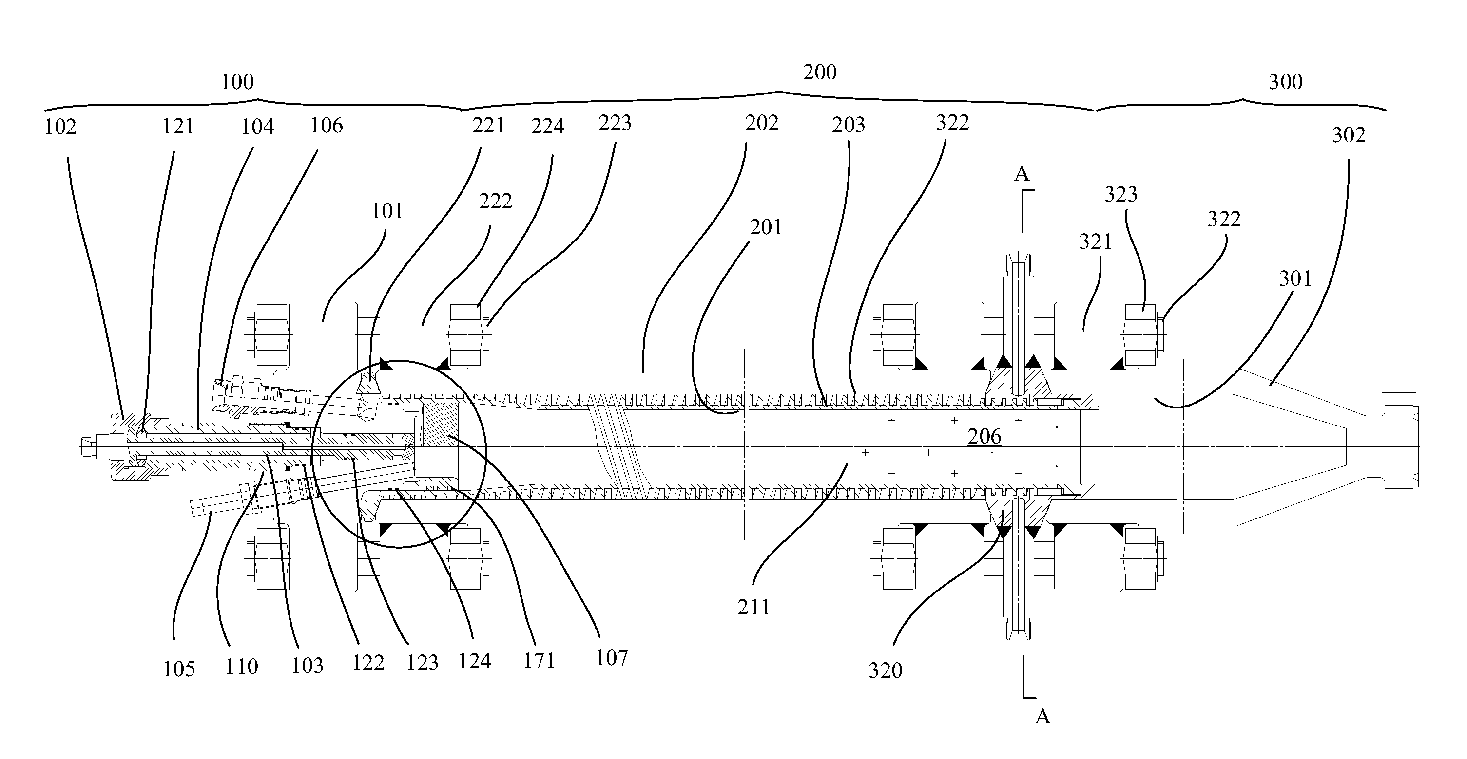
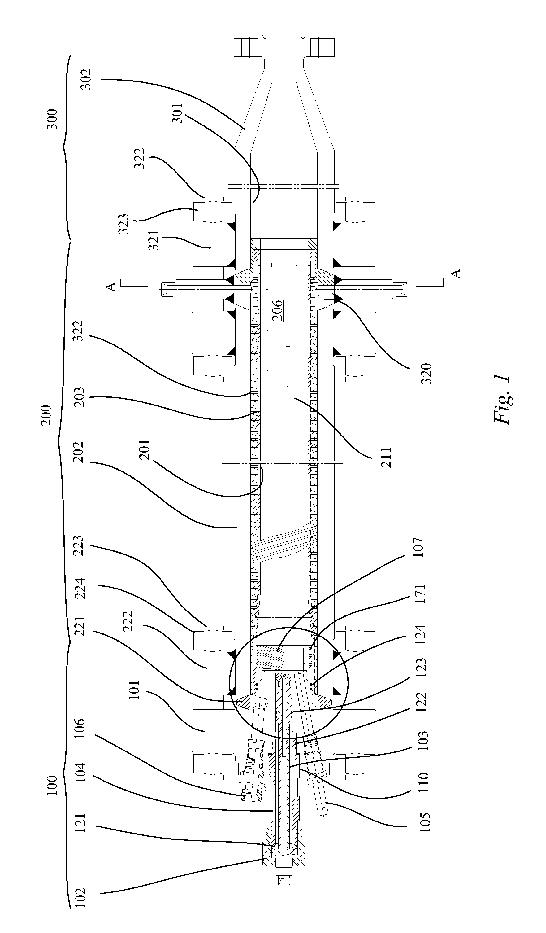
The present patent is about a combustion apparatus for a composite heat carrier generator that can adapt to higher combustion temperatures and pressures. The combustion apparatus includes a combustion chamber and a vaporization chamber connected together. The combustion chamber has a head portion with a fuel receiving nozzle, air receiving nozzle, spark plug, water receiving nozzle, and a cyclone. The fuel receiving nozzle is connected to the fuel spray nozzle, and the air receiving nozzle is sheathed on the fuel spray nozzle. The combustion chamber head portion has an outer shell with air channels, and the interior of the cyclone is provided with a pre-combustion chamber and a cyclone groove. The spray nozzle pipeline has air channels and spray nozzle atomization holes. The fuel spray nozzle has spray nozzle atomization holes and a swirl hole. The technical effects of this patent are a higher combustion temperature and pressure, improved fuel atomization, and better air-fuel mixing.

Problems solved by technology

However, combustion products generated by the device are directly emitted to the atmosphere, which not only pollutes the environment, but also carries away about 10% fuel heat.

Method used


Image

  • Combustion Apparatus of Composite Heat Carrier Generator
  • Combustion Apparatus of Composite Heat Carrier Generator
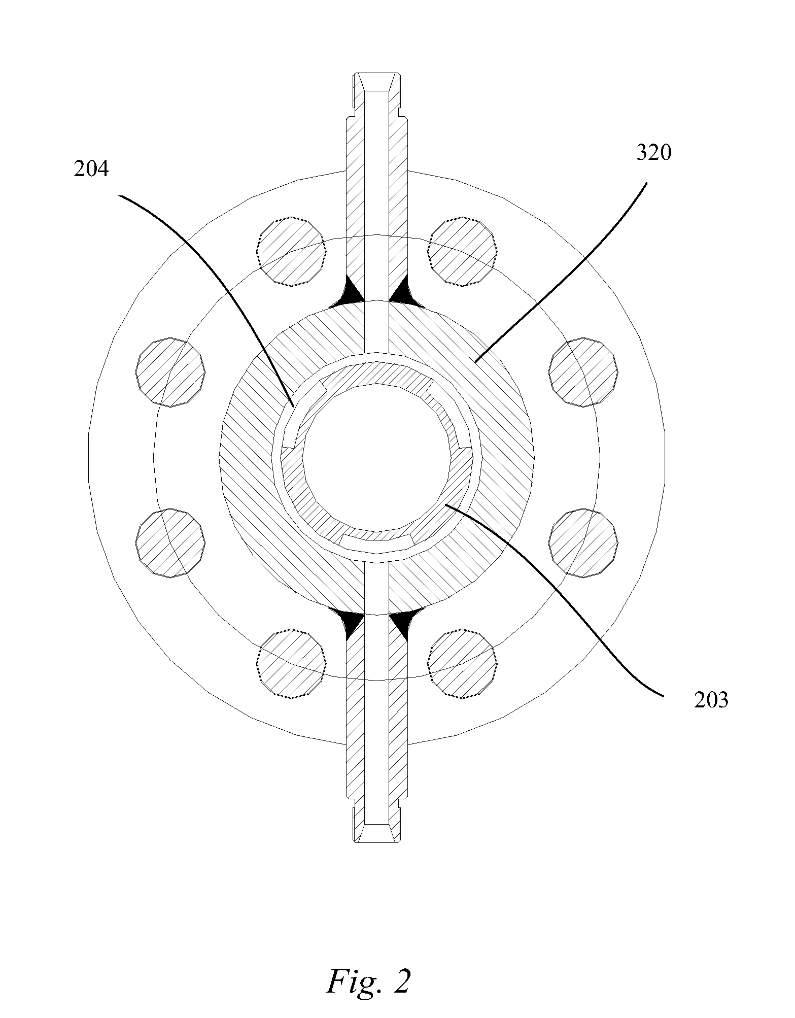
  • Combustion Apparatus of Composite Heat Carrier Generator

Examples


second embodiment

[0039]FIGS. 9 and 10 are structural schematic diagrams of a fuel spray nozzle according to the present disclosure. The combustion apparatus of the present disclosure can not only use diesel oil as fuel, but also use crude oil as fuel. What is required is only replacing the fuel receiving nozzle and the spray nozzle. Compared with the embodiments shown in FIGS. 6-8, the fuel spray nozzle 103 of this embodiment is provided with another group of spray nozzle atomization holes 135 on the outer edge face of the fuel spray nozzle, near the edge. The spray nozzle atomization holes 135 are in communication with the fuel spray holes 133. It can be seen from FIG. 10 that a first group of spray nozzle atomization holes 132 located at the center of the outer edge face of the fuel spray nozzle 103 comprises 2 holes, and a second group of spray nozzle atomization holes 135 located at the edge of the outer edge face of the fuel spray nozzle 103 comprises 6 holes. Moreover, the diameter of the spra...

third embodiment

[0040]FIGS. 11-15 are respectively structural schematic diagrams of a fuel spray nozzle according to the present disclosure. The combustion apparatus of the present disclosure can not only use diesel oil as fuel, but also use natural gas as fuel. What is required is only replacing the fuel receiving nozzle and the fuel spray nozzle. It is to be noted that the part of the outer edge face of the fuel spray nozzle close to the edge is provided with a group of swirl holes 136. These swirl holes 136 are also in communication with the annular groove 134, and a vortex can be formed in the pre-combustion chamber when air is sprayed into the pre-combustion chamber via the swirl holes 136, so that an ignition is easier.

[0041]Compared with the prior art, the beneficial effects of the various embodiment of the present disclosure are:

[0042]1. In the present disclosure, the high-pressure air passes through the cyclone into the combustion chamber via the cyclone, which can preheat air, reduce the ...


PUM


Abstract

A combustion system of a composite heat carrier generator comprises combustion and vaporization chambers. The combustion chamber comprises a main body and a head portion connected thereto. The head portion comprises an outer shell, a cyclone, and fuel receiving, fuel spray nozzle, water receiving, and air receiving nozzles. The fuel receiving and fuel spray nozzles are connected. The air receiving nozzle forms an air inlet cavity in communication with the fuel spray nozzle and the cyclone. The cyclone includes a pre-combustion chamber facing the fuel spray nozzle and a groove. The pre-combustion chamber receives a mixture of fuel and air, and the cyclone groove introduces air.

Description

TECHNICAL FIELD[0001]The present disclosure relates to a composite heat carrier generator and in particular, to a combustion apparatus of a composite heat carrier generator.BACKGROUND[0002]Injection of saturated water steam into an oil layer for the thermal production of thick oils is one of the methods commonly adopted in various countries of the world, and has achieved very good oil production effect and economic benefits. A device for generating saturated water steam is called as a wet saturated water steam generator. The wet saturated water steam generator subjects fuel and air to a low-pressure combustion in a combustion chamber, and heats water in a water pipe to make it vaporize to generate high-pressure saturated steam. The pressure of the steam can be up to 20 MPa (2900 psi), and this pressure can be used for injecting the steam into an oil layer. However, combustion products generated by the device are directly emitted to the atmosphere, which not only pollutes the environ...

Claims


Application Information

Patent Timeline
Patent Type & Authority Applications(United States)
IPC IPC(8): F22B1/18F22B1/22
CPCF22B1/22F22B1/1853
Inventor LIXIN, MELYIZHONG, MELPENFEI, GAOXINGRU, LIJIANZHONG, ZHANGSHIFENG, GUGUOAN, CUI
Owner OTECH SERVICE CANADA
Features
  • R&D
  • Intellectual Property
  • Life Sciences
  • Materials
  • Tech Scout
  • Unparalleled Data Quality
  • Higher Quality Content
  • 60% Fewer Hallucinations
Learn More