Testing device and its calibration method

a testing device and calibration method technology, applied in measurement devices, automated test systems, instruments, etc., can solve the problems of increasing device costs, affecting reducing the calibration efficiency of the test device, so as to achieve the effect of short calibration tim

Active Publication Date: 2016-03-17
ANRITSU CORP
View PDF0 Cites 15 Cited by
  • Summary
  • Abstract
  • Description
  • Claims
  • Application Information

AI Technical Summary

Benefits of technology

[0019]In view of the above, it is an object of the present invention to provide a testing device capable of achieving a short calibration time, and a calibration method employed therein.

Problems solved by technology

Accordingly, if any of these configurations is adopted in the interface unit, significant signal level loss will occur, resulting in that the testing device does not satisfy test performance required by a device under test.
However, the interface unit must have an amplifier excellent in linearity performance, which will raise problems, such as increases in required power and mounting area, and heat dissipation, resulting in an increase in device cost.
In addition, since no consideration is given to a signal input to the testing device, there is a problem that the signal-to-noise ratio of the input signal will be degraded by a value corresponding to the level loss in the interface unit.
However, in general, there is a problem that the level accuracy of an output and an input will be degraded by fluctuation in gain due to fluctuation with time in the performance of the amplifier or due to fluctuation in temperature.
In this case, however, the interface unit must comprise the level detector, which inevitably increases the device mounting area to thereby increase the device cost.
This problem becomes serious in proportion to the number of signal generators.

Method used


Image

  • Testing device and its calibration method
  • Testing device and its calibration method
  • Testing device and its calibration method

Examples


Embodiment Construction

[0098]An embodiment of the invention will be described with reference to the accompanying drawings.

[0099][Configuration of Testing Device]

[0100]Firstly, the configuration of a testing device according to the embodiment of the invention will be described.

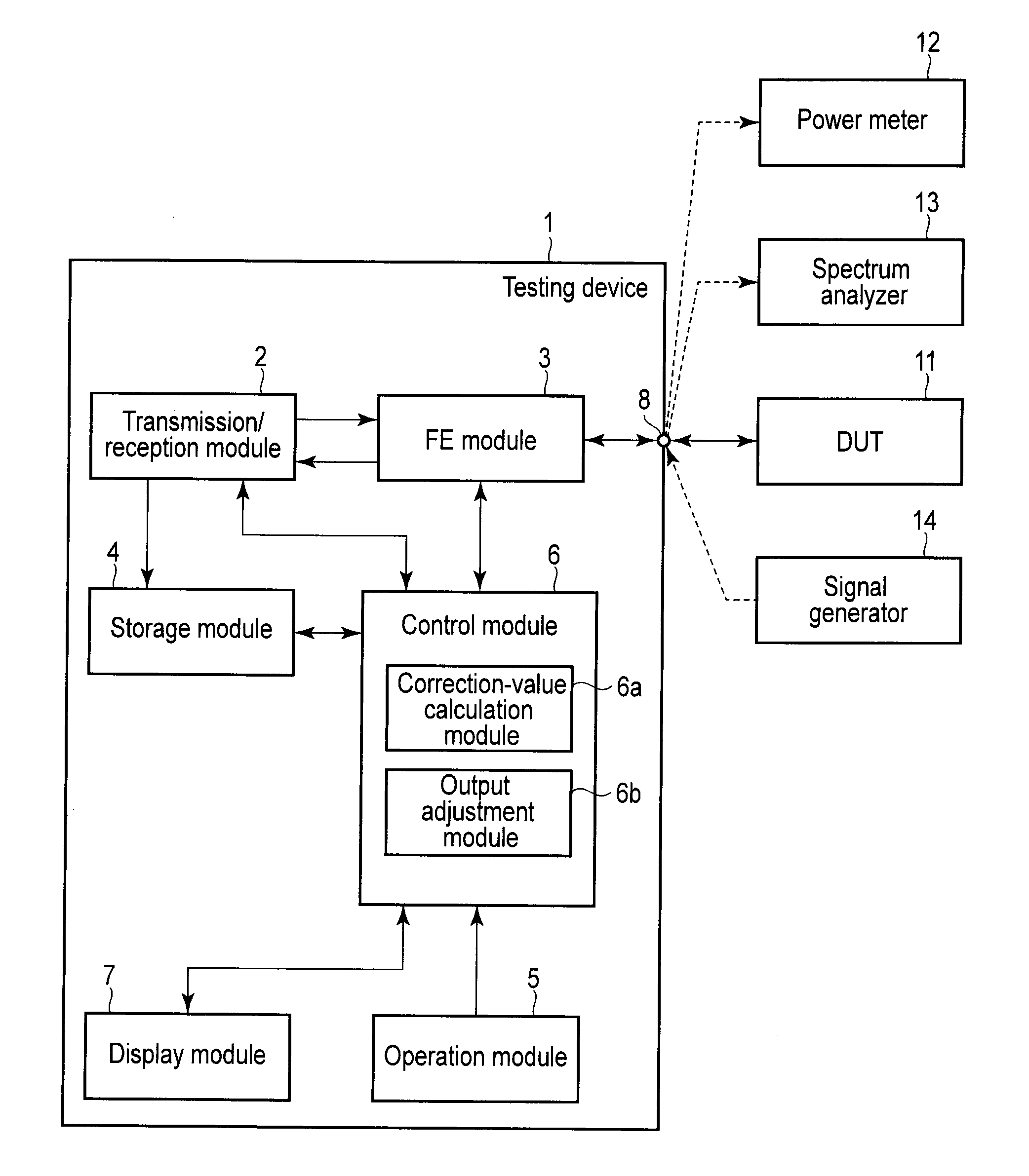
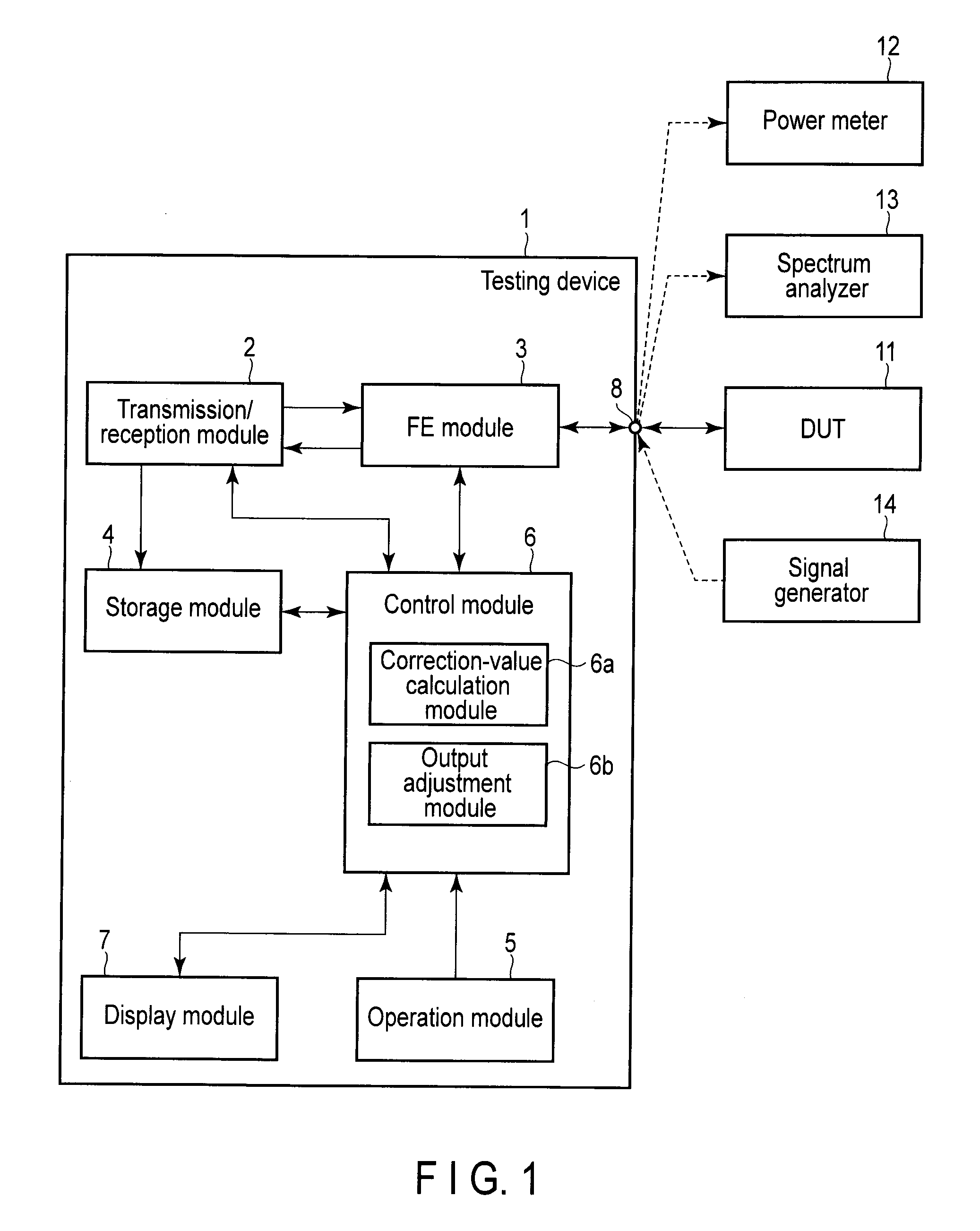
[0101]As shown in FIG. 1, the testing device 1 of the embodiment comprises a transmission / reception module 2, a front end (FE) module 3, a storage module 4, an operation module 5, a control module 6, a display module 7, and input / output terminals 8. The testing device 1 tests a device under test (DUT) 11.

[0102]The testing device 1 also comprises a microcomputer. The microcomputer comprises, for example, a central processing module (CPU), a read only memory (ROM), a random access memory (RAM), an input / output circuit connected to various interfaces, which are not shown. The testing device 1 executes a control program pre-stored in the ROM, thereby causing the microcomputer to function as the transmission / reception module 2, the front ...


PUM


Abstract

According to one embodiment, a testing device includes a signal generator that generates a first signal output to a device under test, a channel selector provided after the signal generator and configured to select one of a plurality of channels, a signal receiver that receives the second signal supplied from the device under test, a correction value calculator that calculates a correction value for calibrating loss of a respective one of the channels, wherein the correction value calculator calculates a correction value for calibrating loss of a respective one of the channels included in the channel selector, based on a signal level received by the signal receiver via a loopback channel, when a calibration-level output state indicating a state where a signal level of the first signal generated by the signal generator reaches a predetermined transmission reference level of calibration is assumed.

Description

CROSS-REFERENCE TO RELATED APPLICATIONS[0001]This application is based upon and claims the benefit of priority from prior Japanese Patent Application No. 2014-189022, filed Sep. 17, 2014, the entire contents of which are incorporated herein by reference.BACKGROUND OF THE INVENTION[0002]1. Field of the Invention[0003]The present invention relates to a testing device for testing, for example, electrical characteristics of a portable device, and a calibration method employed therein.[0004]2. Description of the Related Art[0005]Conventionally, as this type of a testing device, a mobile-device testing system disclosed in, for example, patent document 1 (JP 2003-18104A), is known. The testing device described in patent document 1 comprises a signal generator for generating signals, an interface unit for switching the channel between the signal generator and a device as a measurement target, and a calibration power meter and a calibration receiver connected to the output side of the interf...

Claims


Application Information

Patent Timeline
Patent Type & Authority Applications(United States)
IPC IPC(8): G01R31/317G01R31/28G01R35/00
CPCG01R31/31716G01R35/00G01R31/2834G01R31/3191
Inventor YAMASHITA, KOJIKANNO, HIROFUMIOTANI, TORUOSHIMA, SHINICHIRO
Owner ANRITSU CORP
Why Eureka
Try Eureka