Device, system, method and program for producing fragment model

a technology of fragment model and program, applied in the field of device, system, method and program for creating fragment model, can solve the problems of unlikely error and likely error in the setting of bda and baa, and achieve the effect of improving the accuracy of a calculated resul

Active Publication Date: 2016-03-17
MIZUHO RES & TECH LTD +1
View PDF0 Cites 3 Cited by
  • Summary
  • Abstract
  • Description
  • Claims
  • Application Information

AI Technical Summary

Benefits of technology

[0007]With the above FMO method, when a fragment model is created, a bond detached atom (BDA) and a bond attached atom (BAA), which forms a pair with the BDA, are set by a user for the model on which a calculation is made. That is, the respective paired BDA and BAA are included in different fragment models. The pair of BDA and BAA is called a divisional atom pair. Suitable setting of BDA and BAA improves accuracy of a calculated result obtained by the FMO method.

Problems solved by technology

At this time, when a one-dimensional polymer model such as a protein is subject to the calculation, BDA candidates and BAA candidates are arranged one-dimensionally, and thus an error is unlikely to occur in the setting of BDA and BAA.
However, when a nonmetallic crystal model such as low quartz is subject to the calculation, BDA candidates and BAA candidates scatter three-dimensionally and complicatedly, and thus errors are likely to occur in the setting of BDA and BAA compared to the case of the one-dimensional polymer model.

Method used


Image

  • Device, system, method and program for producing fragment model
  • Device, system, method and program for producing fragment model
  • Device, system, method and program for producing fragment model

Examples


first embodiment

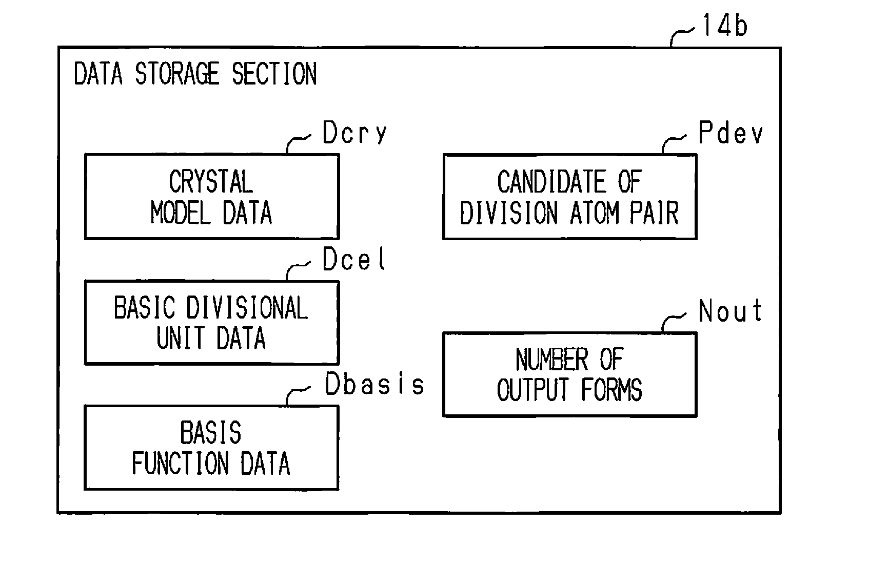
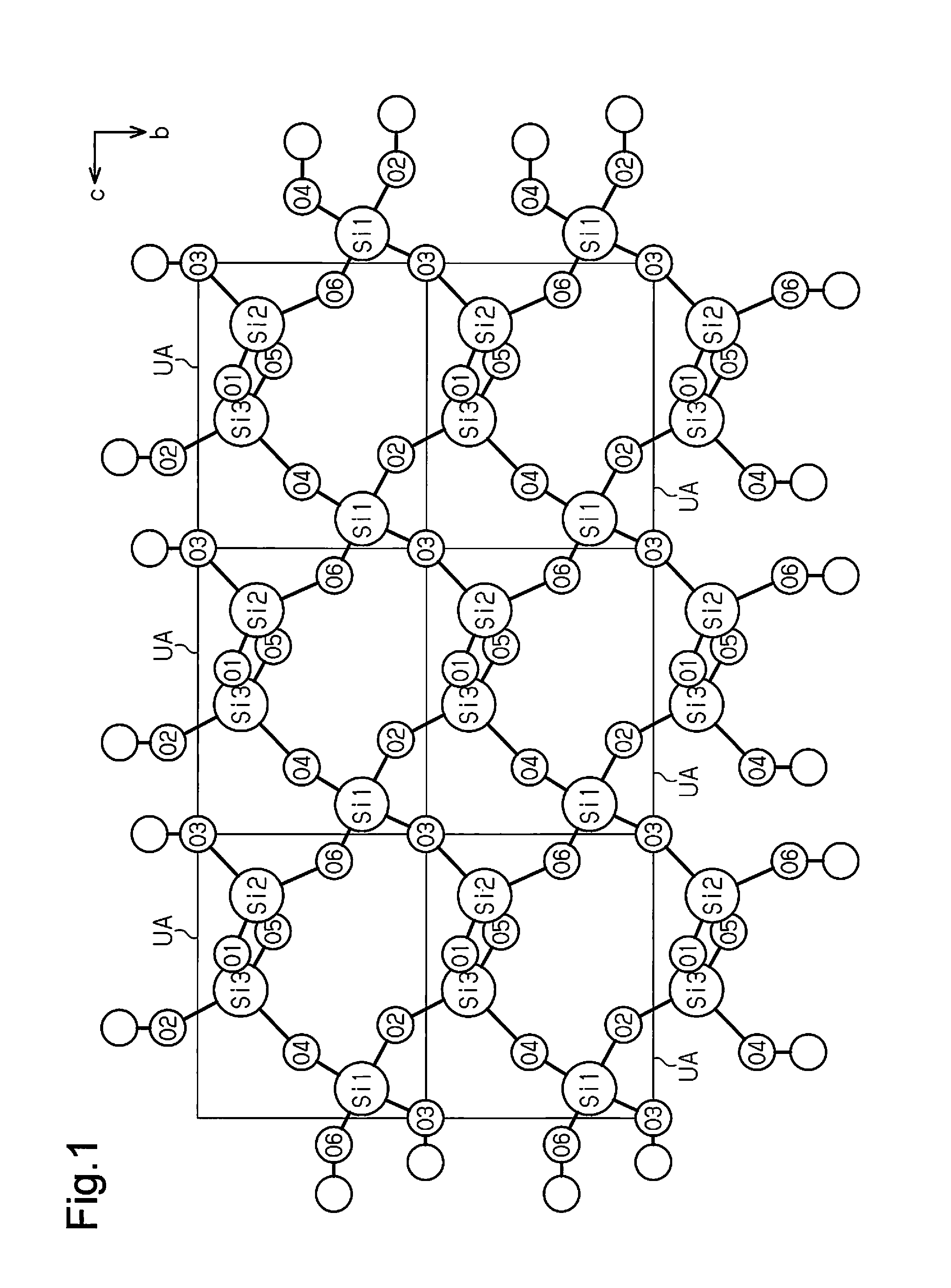
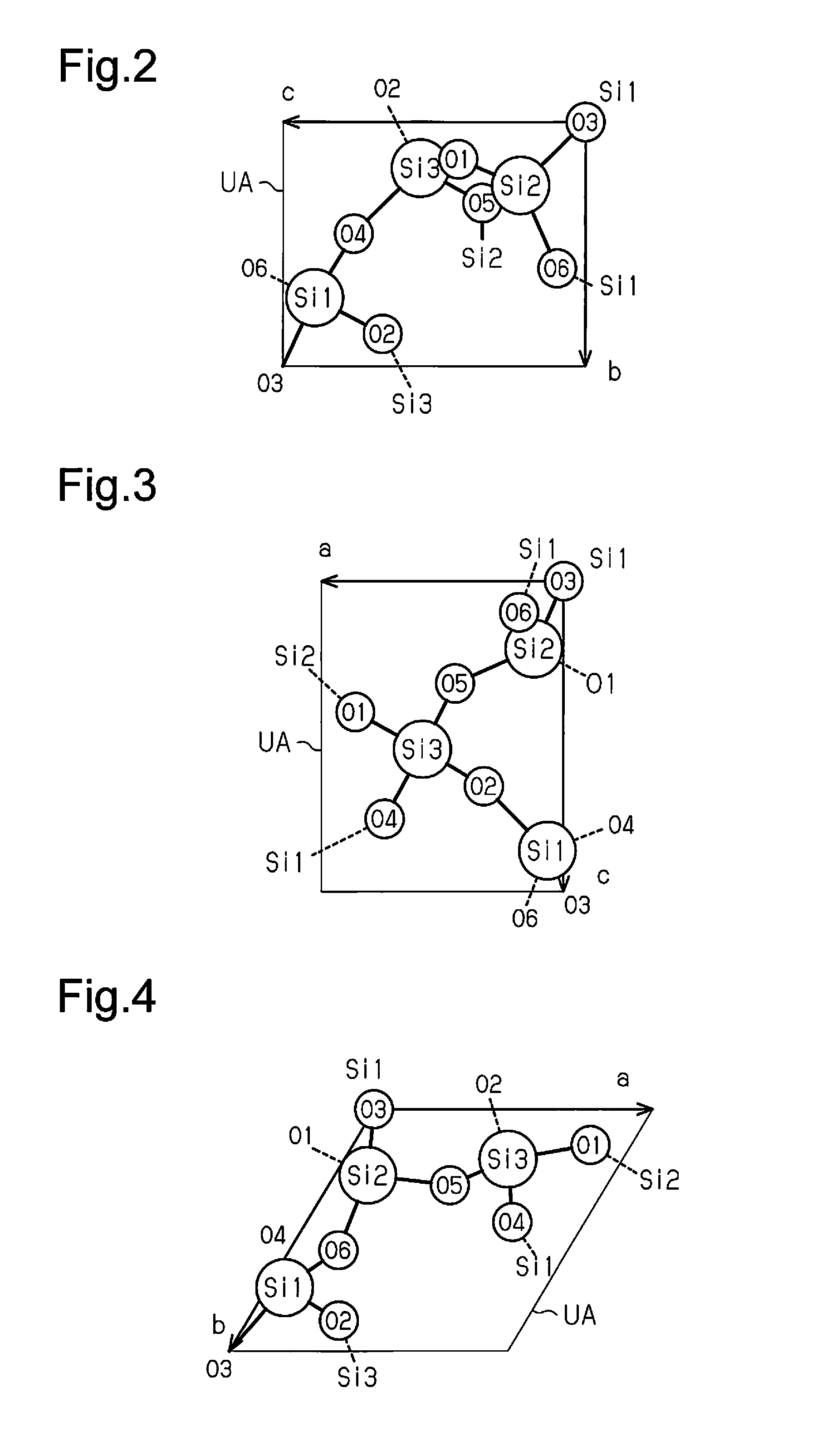
[0036]A first embodiment will be described below with reference to FIGS. 1 to 16. A model of clusters cut out from crystal (hereinafter, a crystal model) and a basic divisional unit that are used for creating a fragment model will be described with reference to FIGS. 1 to 6. Examples of nonmetallic crystal to be the crystal model are covalent crystal such as diamond, boron nitride, silicon, silicon carbide, gallium, and gallium arsenide, or crystal having covalency and ion binding properties such as zeolite, quartz, titanium oxide, aluminum oxide, and zinc oxide. Further, the crystal model may include a point defect, a line defect, a plane defect, a step, which is a stepped portion, or a kink, which is a portion where a stagger for one atom occurs on a line of a step. Further, the target for the crystal model includes crystal in which some atoms are replaced by atoms different from bulk, and crystal to which atoms different from the bulk are added. Further, the target for the crysta...

second embodiment

[0111]A second embodiment will now be described with reference to FIGS. 17 to 22. The second embodiment is different from the first embodiment in that the merging process for again setting some of the created fragment models and the other fragment models as one atom group and creating that atom group as new one fragment model is executed. Therefore, the second embodiment mainly describes points different from the first embodiment, and the same reference symbols as those in the first embodiment are given to the components having the overlapped functions in the first embodiment, and description thereof is omitted.

[0112]In calculations of the electron state of a crystal model using fragment models, calculations of the electron state in respective fragment models can be performed in parallel.

[0113]In such a calculating system, a variation in the size of each fragment subject to parallel computation, namely, a variation in parallel granularity is reduced so that efficiency of the calcula...


PUM


Abstract

A device for creating a fragment model from a crystal model is equipped with a division position identifying section adapted for identifying multiple division atom pairs for multiple atoms contained in the crystal model. The atoms in the division atom pairs are contained in different fragment models. The device is additionally equipped with a model creating section adapted for identifying each of multiple atom groups each composed of atoms bonded to each other in the crystal model and for creating fragment models respectively corresponding to the identified atom groups.

Description

RELATED APPLICATIONS[0001]The present is a National Phase entry of PCT Application No. PCT / JP2013 / 059120, filed Mar. 27, 2013, which claims priority from Japanese Patent Application No. 2012-252456, filed Nov. 16, 2012 the disclosures of which are hereby incorporated by reference herein in their entirety.FIELD OF THE INVENTION[0002]The present disclosure relates to a device, a system, a method, and a program for creating a fragment model.BACKGROUND OF THE INVENTION[0003]Calculation of an interaction energy by using a fragment molecular orbital method (FMO method) is used as one method for analyzing an interaction between a protein and a compound that acts as a ligand of the protein (for example, see Non-Patent Document 1, Non-Patent Document 2, and Non-Patent Document 3).PRIOR ART DOCUMENTSNon-Patent Documents[0004]Non-Patent Document 1: Nakano, Mochizuki et al., Chem. Phys. Lett., 523, pp. 128-133 (2012)[0005]Non-Patent Document 2: Nakano et al., J. Comput. Chem. Jpn., Vol. 6, No. ...

Claims


Application Information

Patent Timeline
Patent Type & Authority Applications(United States)
IPC IPC(8): G06F17/50G16B15/00
CPCG06F17/5009G16B15/00G06F2111/10G06F30/20C30B29/66
Inventor MOCHIZUKI, YUJITSUKAMOTO, TAKAYUKIFUKUZAWA, KAORI
Owner MIZUHO RES & TECH LTD
Why Eureka
Try Eureka