
Reconfigurable logic gates using chaotic dynamics

a technology of chaotic dynamics and logic gates, applied in the field of chaotic computing, can solve the problems of inefficient module compatibility with other digital components, inability to have a large circuit board with dozens of complex components such as operational amplifiers, and difficulty in implementing chaotic dynamics with conventional chaotic computing modules

Inactive Publication Date: 2016-03-24
UNIV OF HAWAII
View PDF13 Cites 6 Cited by
  • Summary
  • Abstract
  • Description
  • Claims
  • Application Information

AI Technical Summary

Benefits of technology

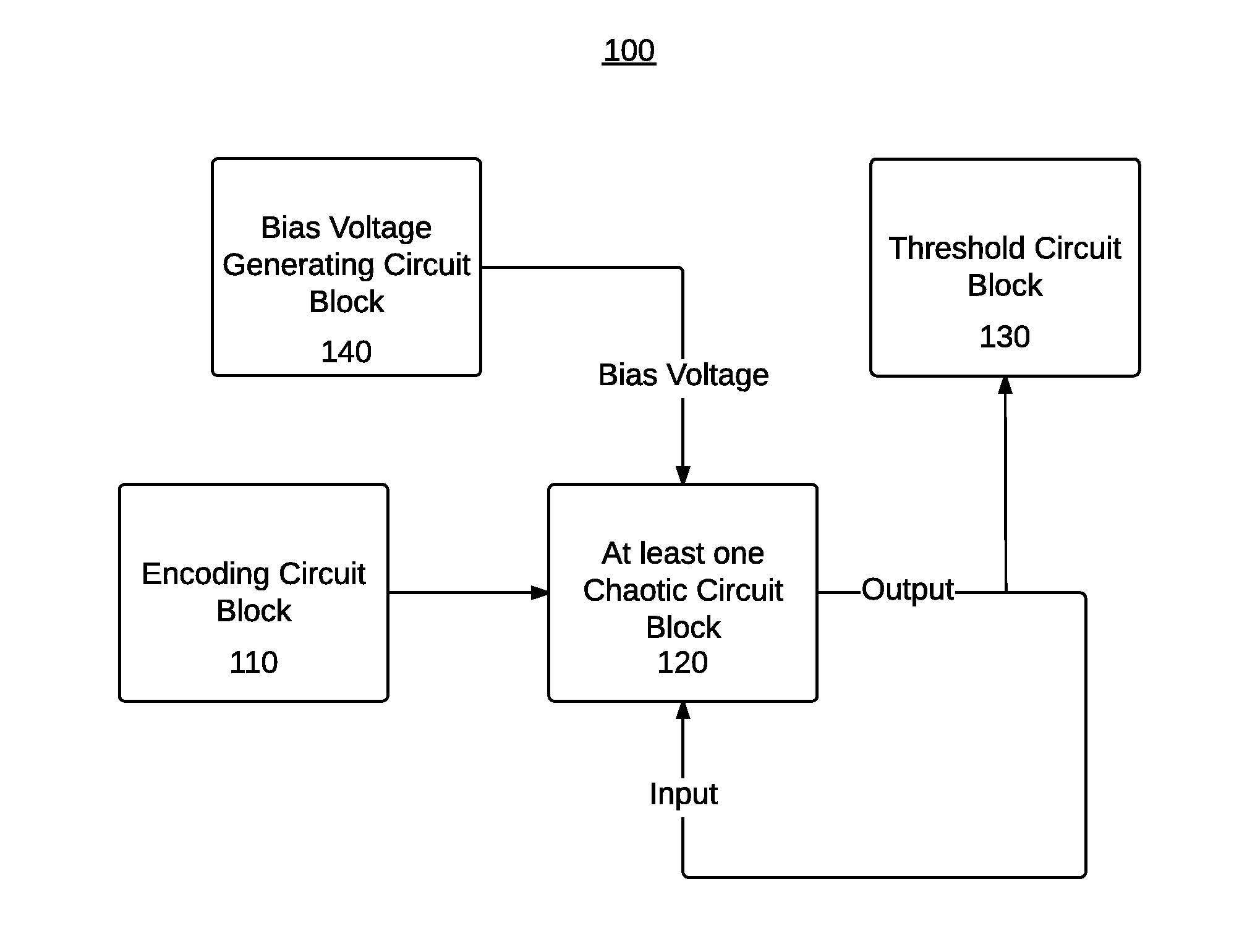
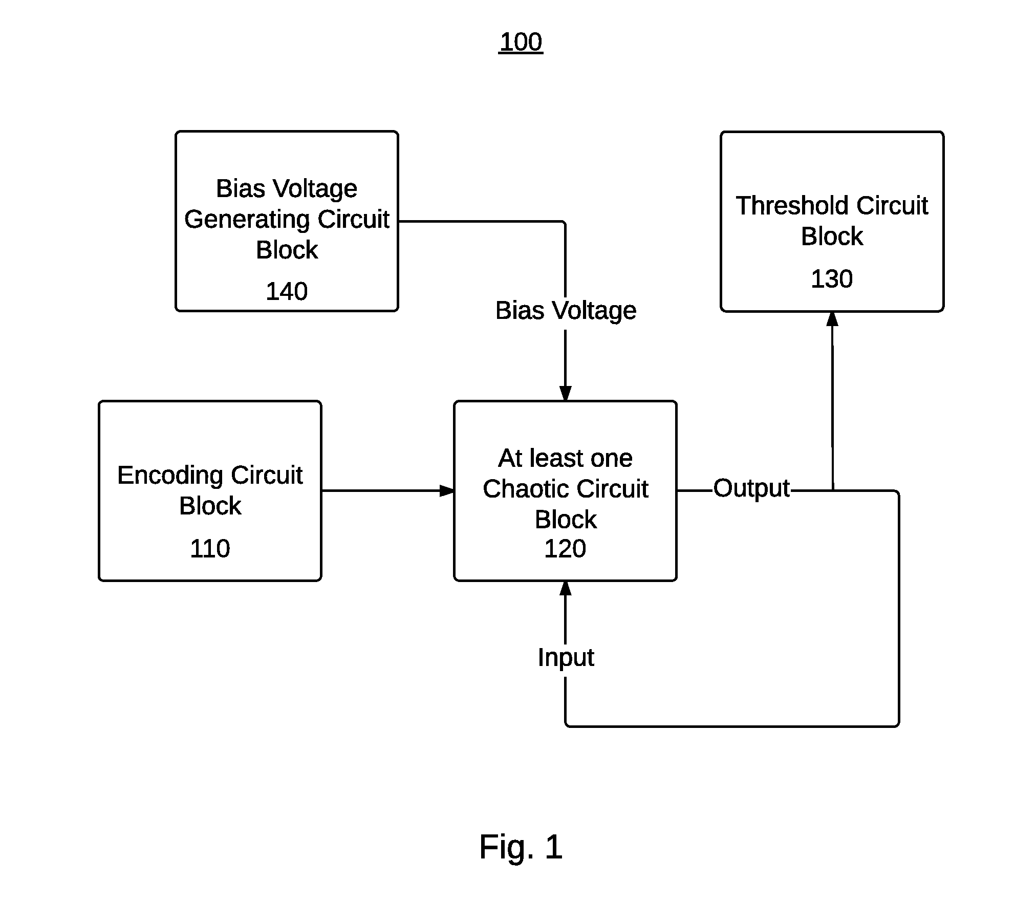
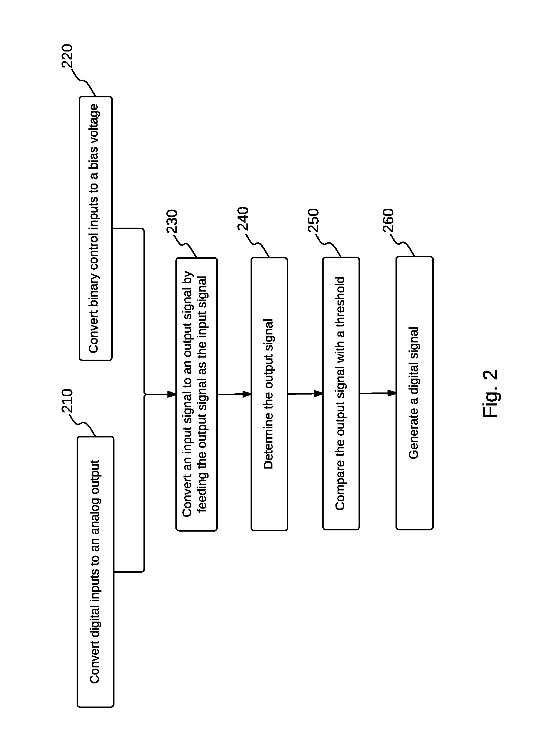
The present invention provides methods and circuit blocks for performing chaos computing. The encoding circuit block converts a plurality of digital inputs to an analog output, while the chaotic circuit block iterates the conversion of an input signal to an output signal. The bias voltage generating circuit block converts a plurality of binary control inputs to a bias voltage, which is used by the threshold circuit block to compare the output signal with a predetermined threshold to generate a digital signal. The technical effect of this invention is to provide a more efficient and accurate method for computing logarithms and other functions using chaos computing.

Problems solved by technology

However, there are practical difficulties in implementing these chaotic dynamics with conventional chaotic computing modules such as operational amplifiers or analog multiplier.
Specifically, considering that the aim is to implement simple logic operations, it is not efficient to have a large circuit board with dozen of complex components such as operational amplifiers.
This means that the module is not fully compatible with other digital components to cascade with or connect to.

Method used


Image

  • Reconfigurable logic gates using chaotic dynamics
  • Reconfigurable logic gates using chaotic dynamics
  • Reconfigurable logic gates using chaotic dynamics

Examples


Embodiment Construction

[0025]The present invention may be understood more readily by reference to the following detailed description taken in connection with the accompanying figures and examples, which form a part of this disclosure. It is to be understood that this invention is not limited to the specific devices, methods, applications, conditions or parameters described and / or shown herein, and that the terminology used herein is for the purpose of describing particular embodiments by way of example only and is not intended to be limiting of the claimed invention. Also, as used in the specification including the appended claims, the singular forms “a,”“an,” and “the” include the plural, and reference to a particular numerical value includes at least that particular value, unless the context clearly dictates otherwise. The term “plurality”, as used herein, means more than one. When a range of values is expressed, another embodiment includes from the one particular value and / or to the other particular va...


PUM


Abstract

The present invention provides apparatuses and methods for chaos computing. For example, a chaos-based logic block comprises an encoding circuit block, at least one chaotic circuit block, a bias voltage generating circuit block, and a threshold circuit block. The encoding circuit block converts a plurality of digital inputs to an analog output. The plurality of digital inputs may comprise at least one data input and at least one control input. At least one chaotic circuit block is configured to iterate converting an input signal to an output signal by feeding the output signal to at least one chaotic circuit as the input signal at each iteration. The bias voltage generating circuit block converts a plurality of binary control inputs to a bias voltage. The threshold circuit block compares the output signal with a predetermined threshold, thereby generating a digital signal.

Description

CROSS REFERENCE TO RELATED APPLICATION[0001]This application claims benefit of U.S. Provisional Application No. 61 / 948,121 filed Mar. 5, 2014. The content of that application are hereby incorporated by reference herein.GOVERNMENT RIGHTS[0002]The subject matter disclosed herein was made with government support under grant numbers STTR-N00014-14-C-0033 and N00014-12-1-0026 awarded by the Office of Naval Research. The Government has certain rights in the herein disclosed subject matter.FIELD OF THE INVENTION[0003]The disclosed invention is in the field of chaos computing.BACKGROUND OF THE INVENTION[0004]Nonlinear, chaotic systems may possess very rich dynamics containing many different behaviors. All of these different behaviors can coexist within the same systems. As an example, a simple nonlinear circuit that can be constructed using a few transistors illustrates a rich library of different behaviors. These different behaviors within the chaotic dynamics can be utilized to implement ...

Claims


Application Information

Patent Timeline
Patent Type & Authority Applications(United States)
IPC IPC(8): H03K19/177H03M1/34
CPCH03K19/17728H03M1/34H03K19/17744
Inventor DITTO, WILLIAMKIA, BEHNAM
Owner UNIV OF HAWAII
Learn More