Method and Apparatus for Uniform Total Body Cryotherapy

a total body and cryotherapy technology, applied in the field of uniform total body cryotherapy, can solve the problems of affecting the treatment process, affecting the treatment effect, and unable to accurately and efficiently apply cryotherapy to more than one region of the body at a time, so as to facilitate the cryotherapy treatment process.

Active Publication Date: 2016-03-31
KUEHNE JONAS
View PDF4 Cites 17 Cited by
  • Summary
  • Abstract
  • Description
  • Claims
  • Application Information

AI Technical Summary

Benefits of technology

[0013]A method and apparatus are provided for the uniform application of cooled air simultaneously to the upper and lower body of an individual undergoing cryotherapy. The present disclosure overcomes the challenges presented by the prior art through the use of a cooling and distribution apparatus capable of creating and maintaining a temperature within a cryochamber ranging between −80 and −160 degrees Celsius. The apparatus of the present disclosure facilitates the cryotherapy treatment process by creating an environment comprising no significant temperature variation between the space occupied by the patients upper and lower extremities.
[0014]Briefly described, one embodiment, among others, is a uniform total body cryotherapy apparatus operative to allow an individual in a cryotherapy chamber to be subjected to the same cold temperatures on their upper and lower extremities at the same time. In use, the apparatus allows active dissemination of cold air in a confined space without the undesired consequence of wind shear commonly caused by forced movement of cold air.
[0017]In one embodiment, cold air is blown downward through the ductwork from a circulating apparatus positioned above the entry side and deflected back up and past the cooling fins of the heat exchangers. Unlike the prior art references, where the person inside the chamber is sprayed with cooling agent onto their skin, at no point does the apparatus of the present disclosure expose any person inside directly to the cooling agent. The temperature of the air is reduced as it follows a path towards the cryochamber ceiling. This will cause the cooled air to slowly sink down towards the bottom of the chamber. The result is an even distribution of cold air from floor to ceiling without any wind shear effect on the person inside the chamber.
[0019]In one embodiment of the present disclosure, the cooling agent may be recycled as part of a closed loop. In this embodiment, the cooling agent is passed through an initial set heat exchangers but not discarded through a vent pipe. Rather than being discarded, the used cooling agent passes through a line connected to a separate set of heat exchangers where it facilitates the cooling of another cryochamber. The second cryochamber is not as cool as the original chamber. This establishes a gradient of chambers whereby the user may begin by entering a chamber with the highest temperature and gradually work their way into successively colder chambers.
[0022]Having a primary chamber separated from other ancillary chambers functions to minimize temperature loss from the chamber with the lowest temperature. Temperature loss within a cyrochamber can lead to wasteful energy expenditures. Numerous other features, objects and advantages of the invention will become apparent from the following description when read in conjunction with the accompanying drawings.

Problems solved by technology

Advances in the art have inspired more complex proposals for effectuating a desired treatment method through decreasing tissue temperature on and around the impacted area.
While the '804 patent expands beyond just the hands and feet of the user, it lacks the ability to accurately and efficiently apply cryotherapy to more than one region of the body at a time.
The aforementioned techniques place significant constraints on how cold and for how long a practitioner could apply cryotherapy on their patient.
Though these approaches were beneficial for the time, design constrictions only allowed small regions to be targeted and for a short period of time.
Technological restrictions of the period meant temperatures could only be as cold as ice and not sustained for very long due to melting.
The manner in which cooling air is introduced into the chambers necessarily causes frigid air to accumulate in the bottom of the cryochamber.
In practice, clinicians are limited in the amount of time they can allow patients to spend in these chambers and must focus on the exposure time of the lower extremities alone or risk harming their patients.
Skin burns to the lower extremities are a well known risk associated with these devices.
All of the cyrochambers heretofore known are further limited because they are incapable of treating the entire body of the person within.
As a result, they do not supply cooling air to the head and neck of the user.
The head and neck comprise many cold receptors and ignoring this region has a deleterious impact on the treatments efficacy.
However, attempts at this methods have proven ineffective.
The movement of cold air results in wind shear.
This wind shear factor unnecessarily exposes the patient to a high risk of skin burn causing medical professionals to dismiss this as a viable treatment option.
Furthermore, neither the '652 patent nor the '930 patent teaches an adequate means for ensuring the cold air introduced into the chambers does not escape.
Temperatures within the chambers may range from minus eighty to minus one hundred and sixty degrees Celsius and yet all of the cryotherapy chambers heretofore known utilize conventional insulation methods which have proven inadequate for sustaining these temperatures.
Temperature loss within a cyrochamber can lead to wasteful energy expenditures.

Method used


Image

  • Method and Apparatus for Uniform Total Body Cryotherapy
  • Method and Apparatus for Uniform Total Body Cryotherapy
  • Method and Apparatus for Uniform Total Body Cryotherapy

Examples


Embodiment Construction

[0031]Illustrative embodiments of the invention are described below. The showings are for purposes of illustrating preferred embodiments and not for purposes of limiting the same. The following explanation provides specific details for a thorough understanding of an enabling description for these embodiments. One skilled in the art will understand that the invention may be practiced without such details.

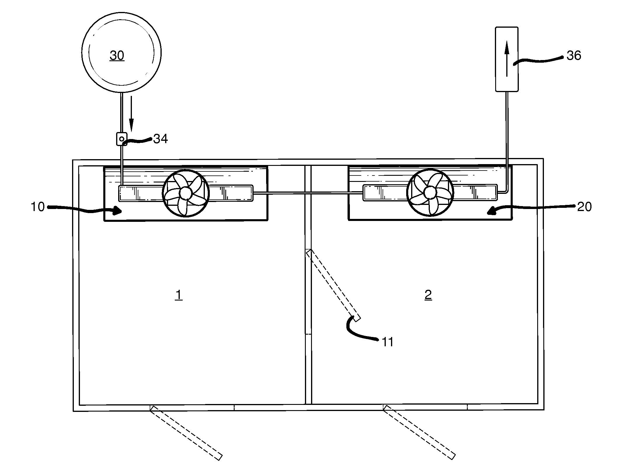
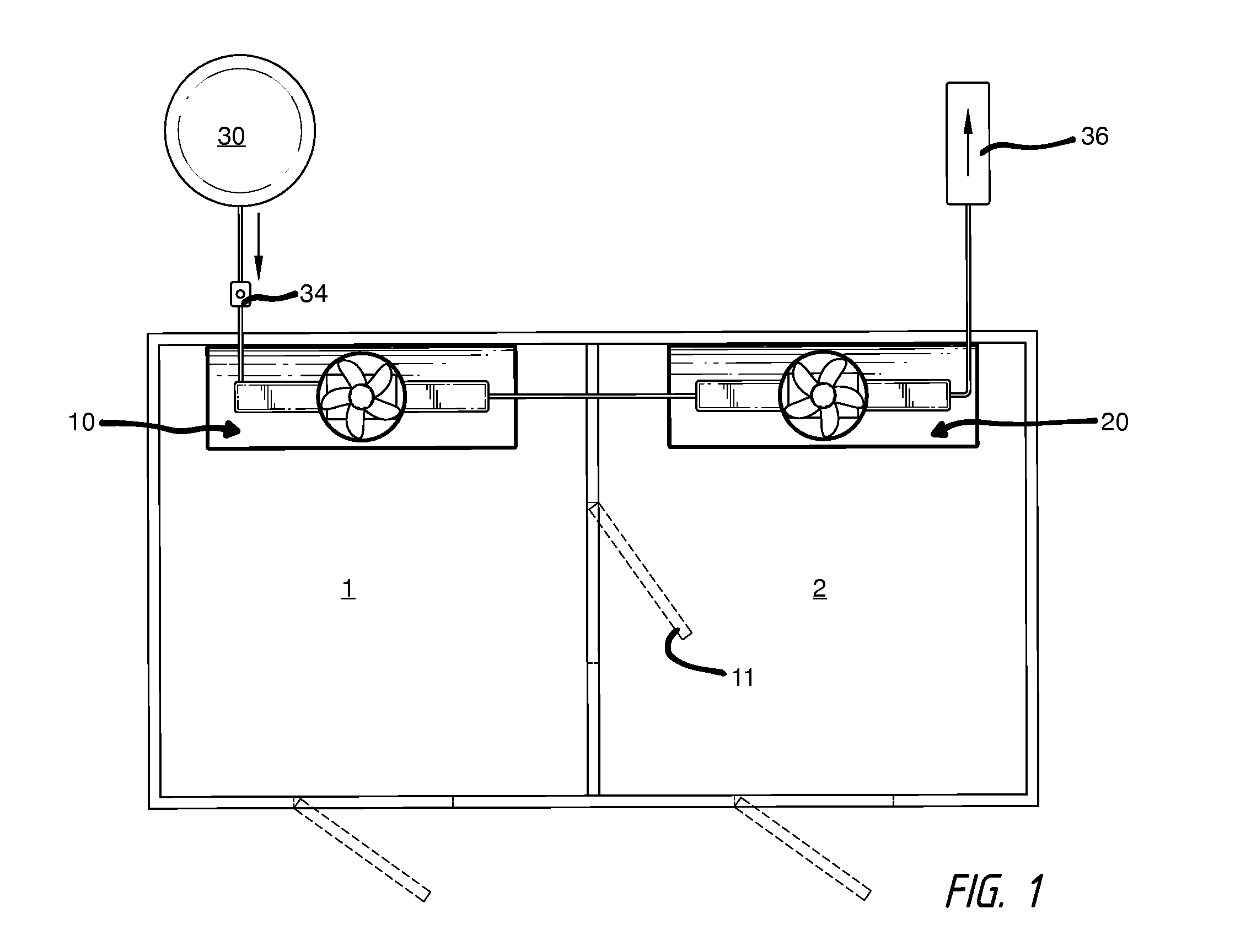
[0032]FIG. 1 is an overhead schematic depicting an first exemplary cryochamber utilizing the method and apparatus of the present disclosure. The exemplary embodiment illustrated therein depicts a cryochamber comprising at least two subchambers. A primary chamber 1 and a secondary chamber 2 are interconnected and separated by an access door 11 which remains closed during normal operation. This embodiment further comprises at least two cooling apparatuses, a first apparatus 10 located in the primary chamber 1 and a second apparatus 20 located in the secondary chamber 2. However, in var...


PUM


Abstract

In accordance with one embodiment, a uniform total body cryotherapy method and apparatus operative to allow an individual in a cryotherapy chamber to be subjected to the same cold temperatures on their entire body at the same time. In use, the apparatus allows active dissemination of cold air in a confined space without the undesired consequence of wind shear commonly caused by forced movement of cold air.

Description

CROSS-REFERENCE TO RELATED APPLICATIONS[0001]None.NOTICE OF COPYRIGHT AND TRADE DRESS[0002]A portion of the disclosure of this patent document contains material which is subject to copyright protection. This patent document may show and / or describe matter which is or may become trade dress of the owner. The copyright and trade dress owner has no objection to the facsimile reproduction by any one of the patent disclosure as it appears in the Patent and Trademark Office patent files or records, but otherwise reserves all copyright and trade dress rights whatsoever.TECHNICAL FIELD[0003]The present disclosure relates generally to methods and apparatuses for exposing a person's body to cold temperatures as a means of alleviating pain, decreasing inflammation, or achieving a general sense of well-being. More particularly, the present disclosure relates to a method and apparatus for facilitating the application of cryotherapy precisely and uniformly throughout the entire body of a person u...

Claims


Application Information

Patent Timeline
Patent Type & Authority Applications(United States)
IPC IPC(8): A61F7/00F25D17/06
CPCA61F7/0053A61F2007/0056F25D17/06A61F2007/0064F25D3/102F25D17/067F25D2317/063A61F2007/0062
Inventor KUEHNE, JONAS
Owner KUEHNE JONAS
Why Eureka
Try Eureka