Suspension bearing device, motor vehicle equipped with such a strut bearing device and manufacturing method
- Summary
- Abstract
- Description
- Claims
- Application Information
AI Technical Summary
Benefits of technology
Problems solved by technology
Method used
Image
Examples
Embodiment Construction
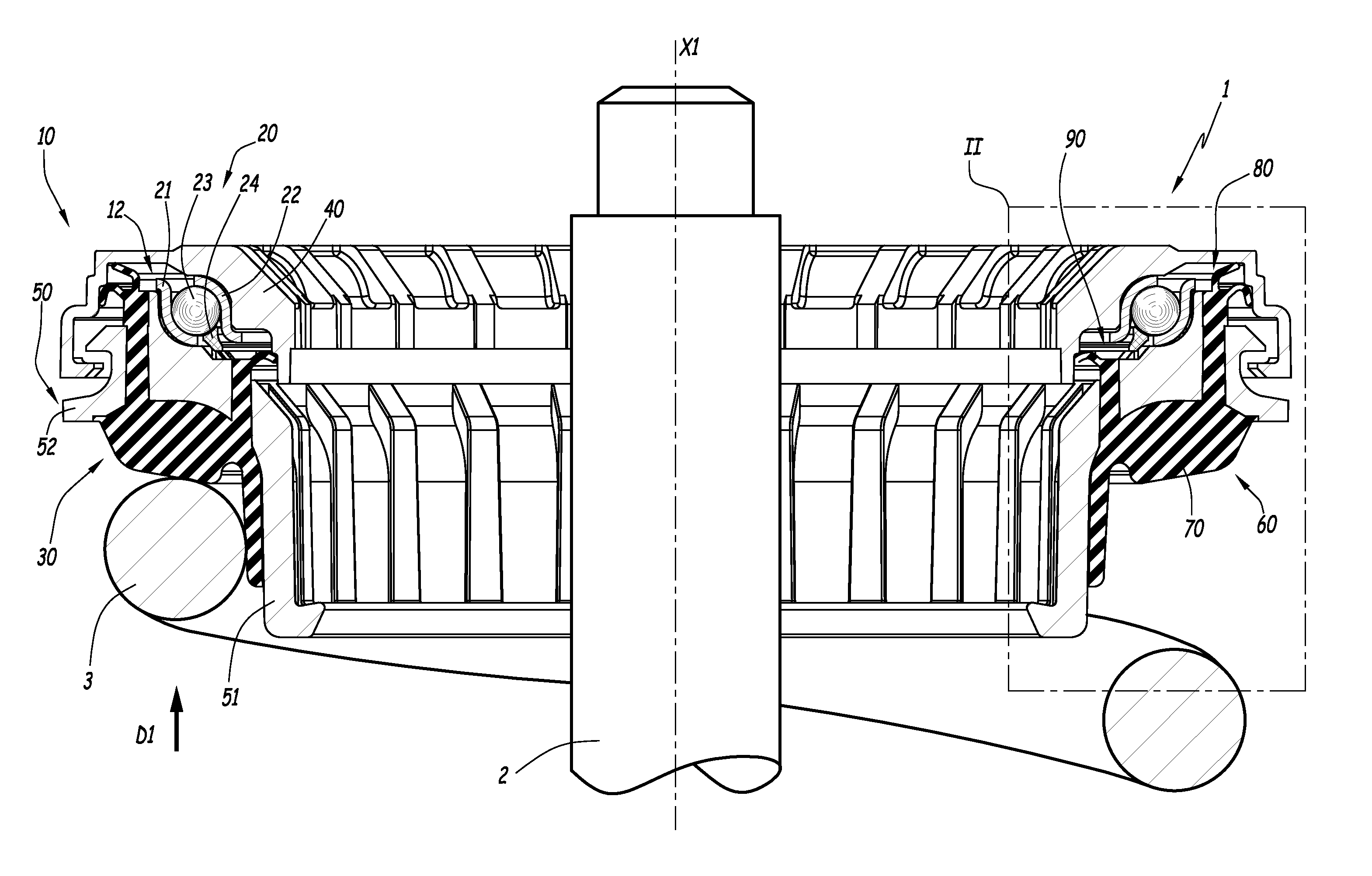
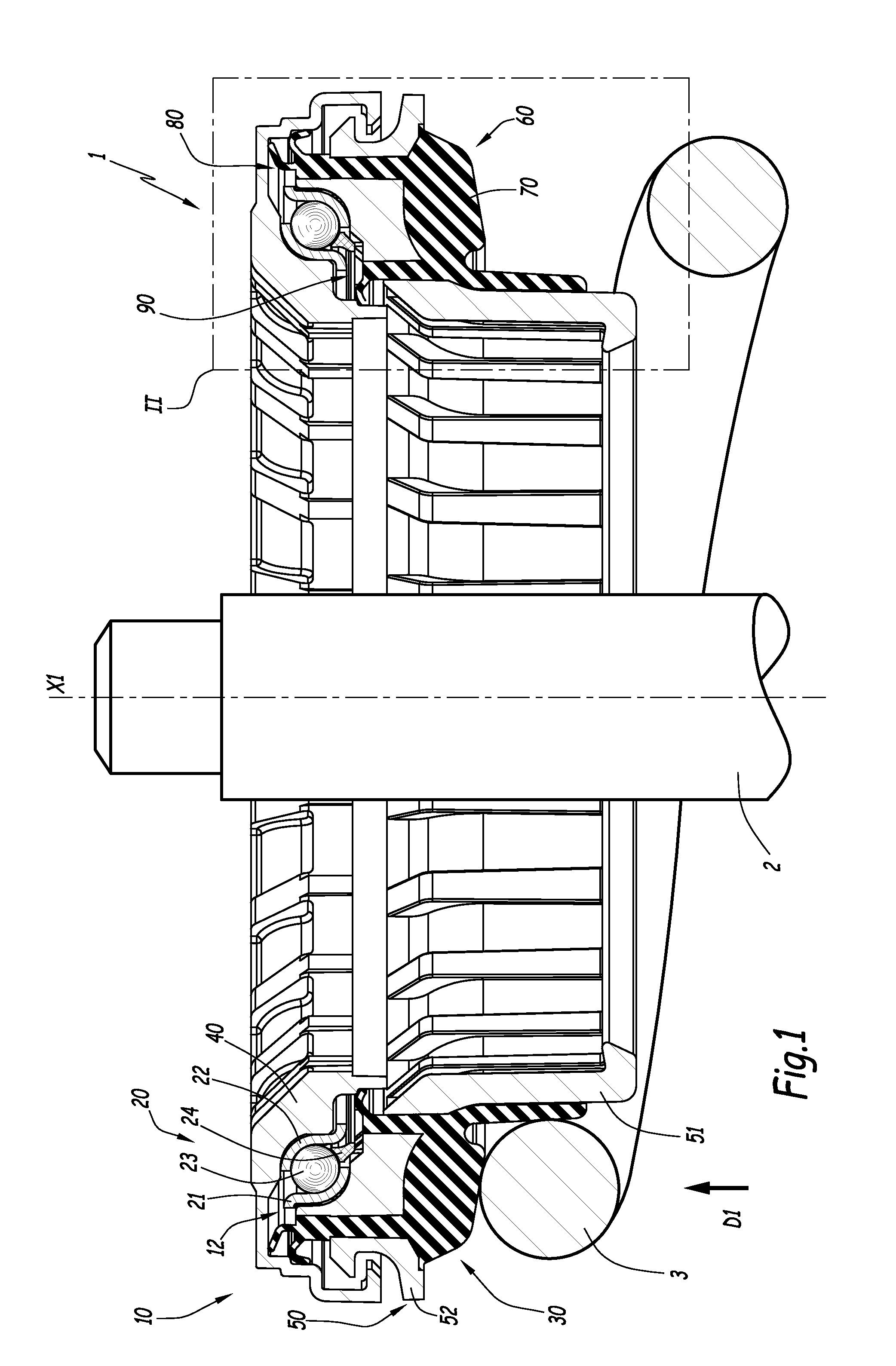
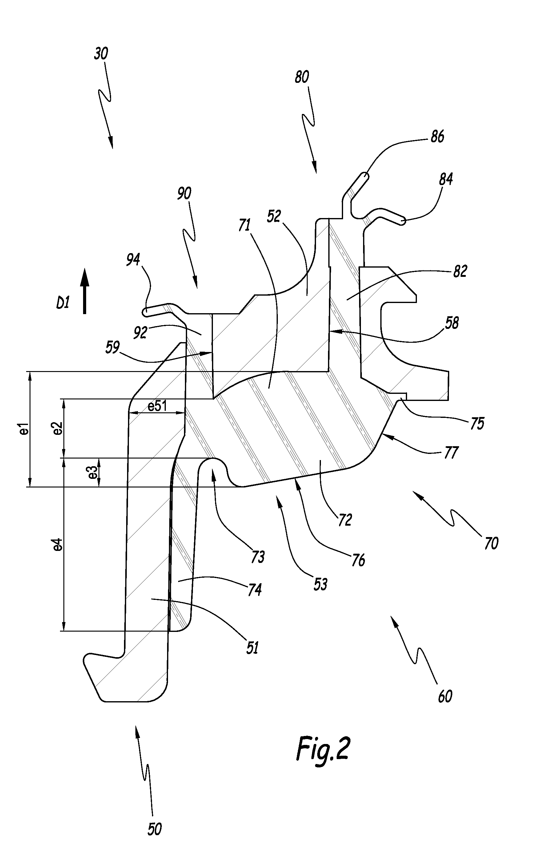
[0036]FIGS. 1 and 2 show a suspension bearing device 10 according to the invention and its constitutive elements. Device 10 is configured to equip a strut 1, partially shown on FIG. 1, of a motor-vehicle suspension system.
[0037]Strut 1 supports an axle and a wheel of a vehicle, not shown for simplification purposes. Strut 1 extends along a central axis X1 placed in a substantially vertical direction when the wheel of the vehicle rests on a flat ground. Strut 1 comprises a damper rod 2, a suspension spring 3 and the suspension bearing device 10. Rod 2 and spring 3 are partially and schematically shown on FIG. 1. Strut 1 also comprises a piston body and a bumper, not shown for simplification purposes. Damper rod 2 and piston body constitute a damper piston belonging to strut 1.
[0038]Device 10 has an overall a shape of revolution about axis X1. Device 10 comprises a rolling bearing 20, a lower cup 30 and an upper cup 40. Bearing 20 is positioned in a chamber 12 delimited between cups 3...
PUM
| Property | Measurement | Unit |
|---|---|---|
| Thickness | aaaaa | aaaaa |
| Thickness | aaaaa | aaaaa |
| Thickness | aaaaa | aaaaa |
Abstract
Description
Claims
Application Information
 - R&D
- Intellectual Property
- Life Sciences
- Materials
- Tech Scout
- Unparalleled Data Quality
- Higher Quality Content
- 60% Fewer Hallucinations
Browse by: Latest US Patents, China's latest patents, Technical Efficacy Thesaurus, Application Domain, Technology Topic, Popular Technical Reports.
© 2025 PatSnap. All rights reserved.Legal|Privacy policy|Modern Slavery Act Transparency Statement|Sitemap|About US| Contact US: help@patsnap.com


