
windraider

a technology of wind power and rudder, which is applied in the direction of mechanical equipment, machines/engines, electric generator control, etc., can solve the problems of decreasing lift, increasing in the reverse direction, and no one being able to achieve oscillation

Active Publication Date: 2016-04-07
LOVAS ANDREW
View PDF22 Cites 4 Cited by
  • Summary
  • Abstract
  • Description
  • Claims
  • Application Information

AI Technical Summary

Benefits of technology

The patent is about a new type of wind turbine that can generate more electricity economically and efficiently. By using better materials and better fabrication capabilities, the Tower Models are able to produce more electricity than current wind turbines. They can also reduce the cost of electricity from traditional sources and help to slow global warming. The invention is designed to be quickly deployed in large numbers and has the potential to reduce US dependence on fossil fuels by a significant amount in a short time.

Problems solved by technology

None was able to achieve oscillation.
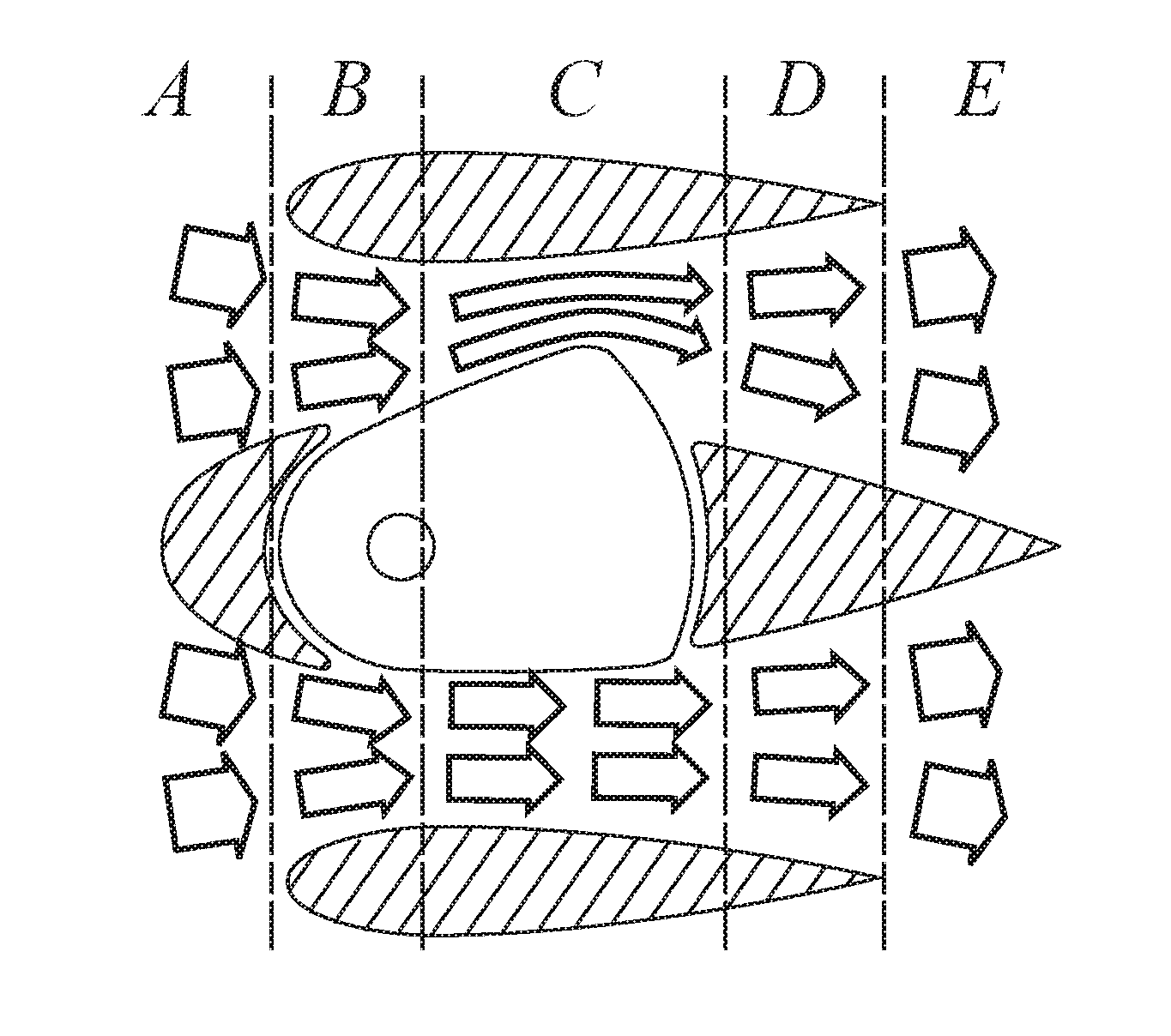
The problem is that as a symmetrical articulated airfoil with a zero angle of attack to the wind rotates, lift diminishes in the direction its tail rotates toward; while at the same time it increases in the reverse direction.
It also happened that during a trial run before the camera was mounted and recording begun, the inadequately secured Wind Wing model blew off the top of the car and went bouncing down the runway.
Facilities to test the limits of this are beyond the access of the inventor. but there is no reason to believe that the Wind Wing might not be able to convert wind energy into mechanical energy in speeds in excess of 60 MPH and beyond—except that no generator thus far invented appears capable of withstanding the shock of oscillating motion such speeds would produce.
Perhaps most importantly, the Wind Wing is uncannily deployable.

Method used


Image

  • windraider
  • windraider
  • windraider

Examples


Embodiment Construction

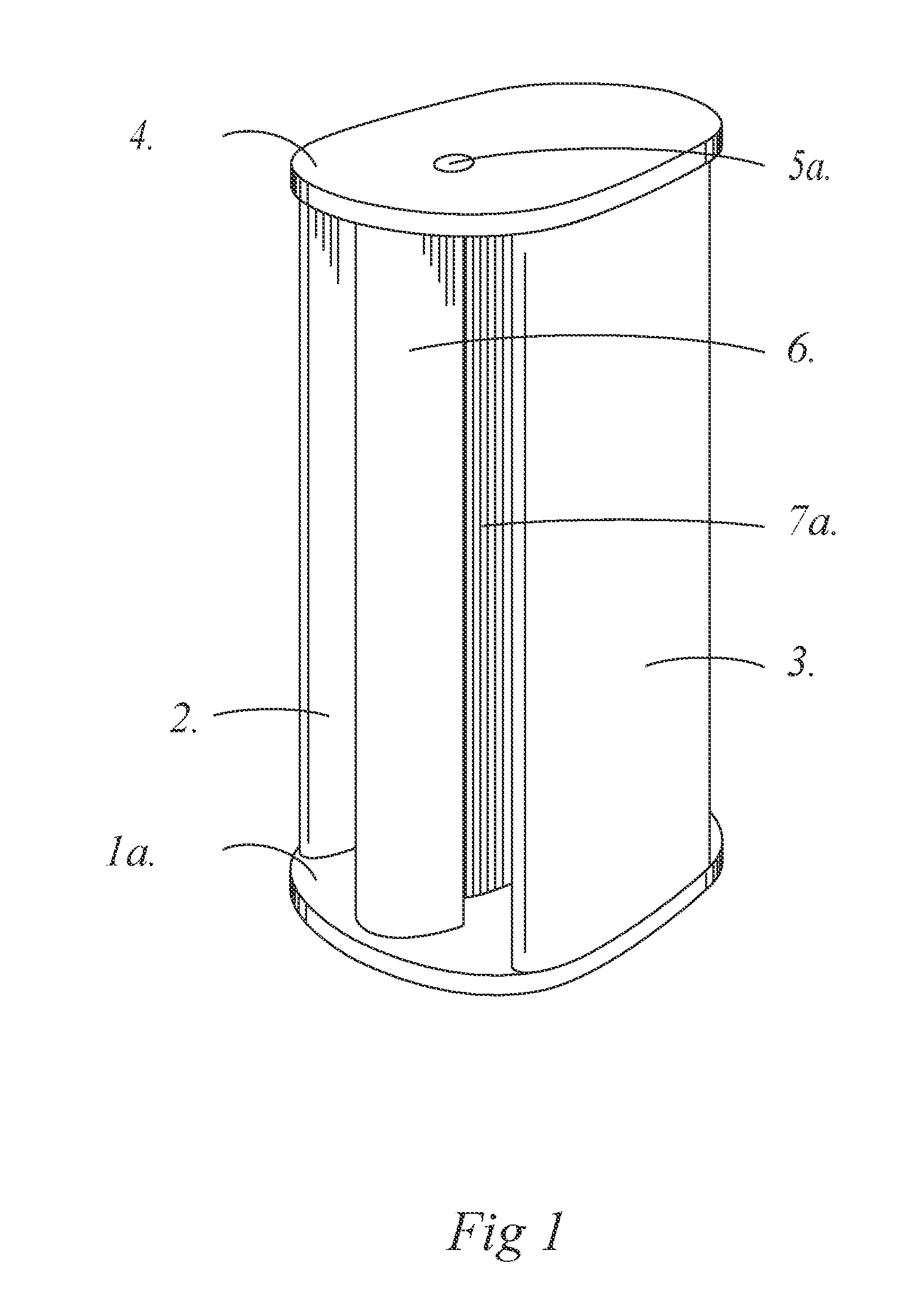
[0244]FIG. 1 is a perspective view of the outside of a Wind Wing $20 Model forward, port of, and slightly above it, which illustrates parts of its Floor (1a.), Starboard outside airfoil (2.), Port outside airfoil (3.), Roof (4.), Mast (5a.), Forward nacelle (6.) and Oscillating wing (7a.).

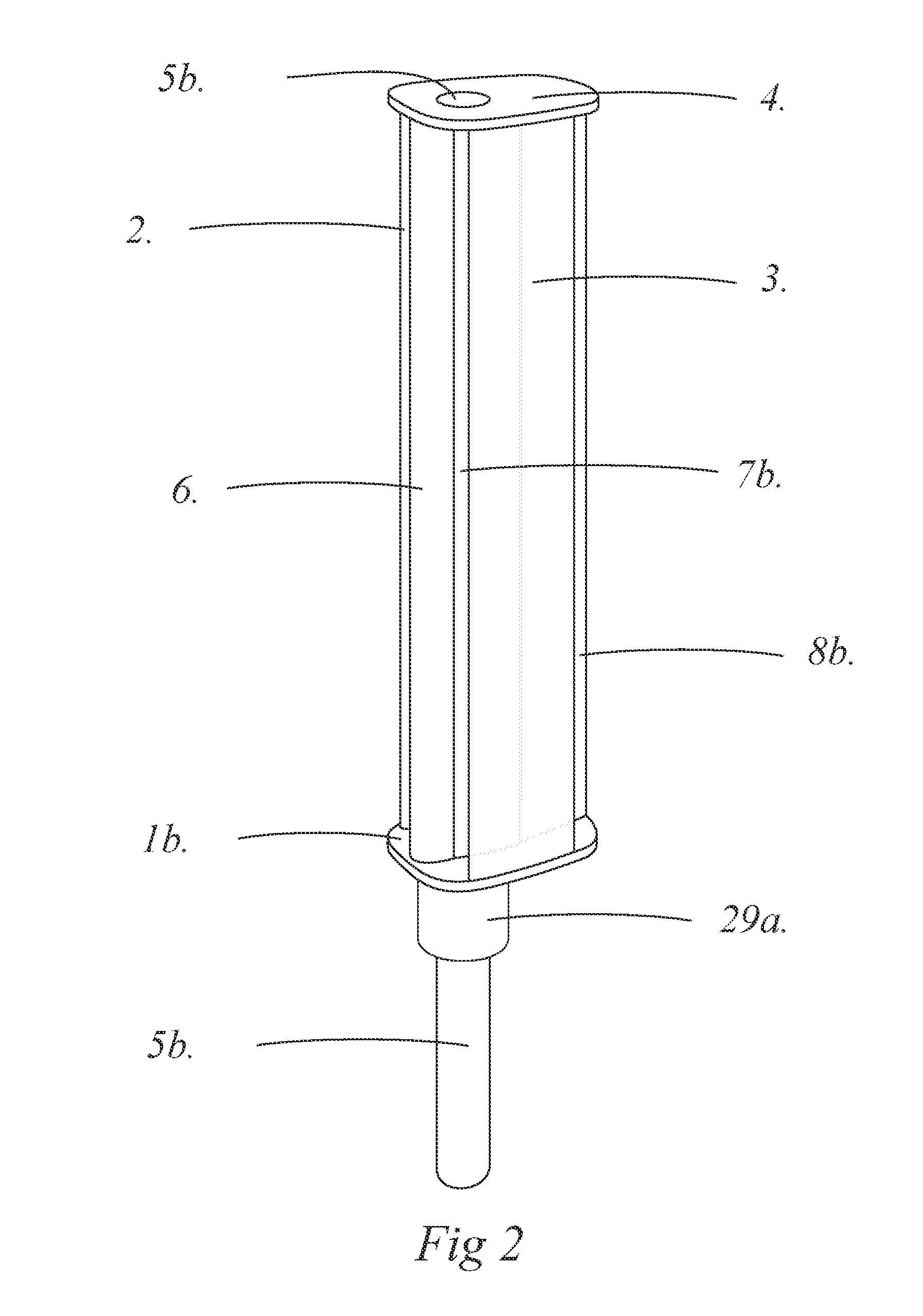
[0245]FIG. 2 is a perspective view of the outside of a Wind Wing Tower Model forward, port of, and slightly above it, which illustrates parts of its Floor (1b.), Starboard outside airfoil (2.), Port outside airfoil (3.), Roof (4.), Mast (5b.), Forward nacelle (6.), Oscillating wing (7b.) and Torque transmitter / Generator cover (29a).

[0246]FIG. 3 (a.) is a top down view of a Wind Wing $20 Model with its Roof (4.) removed which illustrates parts of its Floor (1a.), Starboard outside airfoil (2.), Port outside airfoil (3.), Mast (5a.), Forward nacelle (6.), Oscillating wing (7a.) and Aft nacelle (8a.), Outside permanent magnet array holder notch (8a. 1.), the lattermost accommodating the Wind Wing Elec...


PUM


Abstract

The Windraider process, the Wind Wing, and the Armstrong electrical generator are innovations in converting wind energy into electrical energy which show significant promise in improving the economic and ergonomic utility of wind power.

Description

CROSS-REFERENCE TO RELATED APPLICATIONS[0001]1. U.S. Pat. No. 8,734,082[0002]Filing Date: Dec. 17, 2012[0003]Title of Invention: Wind Wing[0004]Relation to current application: Earlier engineering implementation of the wind energy to mechanical energy conversion mechanism of Windraider.[0005]2. U.S. Pat. No. 8,860,240[0006]Filing Date: Feb. 7, 2014[0007]Title of Invention: Wind Wing Electrical Generator[0008]Relation to current application: Earlier engineering implementation of the mechanical energy to electrical energy conversion mechanism of Windraider.[0009]3. Provisional Patent Application No. 62 / 039,493[0010]Filing Date: Aug. 20, 2014[0011]Title of Invention: Armstrong Electrical Generator[0012]Relation to current application: Advanced engineering features for the Wind Wing (1. above) and the Wind Wing Electrical Generator (2. above).[0013]4. Provisional Patent No. 62 / 148,046[0014]Filing Date; Apr. 15, 2015[0015]Title of Invention: Windraider[0016]Relation to current applicatio...

Claims


Application Information

Patent Timeline
Patent Type & Authority Applications(United States)
IPC IPC(8): F03D3/06F03D3/04H02K35/04F03D9/00
CPCF03D3/062H02K35/04F03D3/0409F03D9/002F03D5/06Y02E10/70
Inventor LOVAS, ANDREW
Owner LOVAS ANDREW
Learn More