
Fluorescence removal from raman spectra by polarization subtraction

Inactive Publication Date: 2016-04-14
ALAKAI DEFENSE SYST
View PDF10 Cites 14 Cited by
  • Summary
  • Abstract
  • Description
  • Claims
  • Application Information

AI Technical Summary

Benefits of technology

The patent describes a method of detecting explosives using UV Raman spectroscopy. This method involves using a polarization technique to extract UV Raman spectra from wavelength sources such as Nd3+:YAG lasers, which are cheaper, easier to maintain, and more rugged than previous options. By using polarization methods, UV Raman spectroscopy can be acquired using these types of lasers for standoff detection of explosives. The use of a polarized UV laser source at a wavelength of ˜248 nm or ˜320-360 nm can provide significant improvement over current DUV Raman spectroscopy without using polarization methods. A portable instrument with an adjustable polarizer can be used for quick and easy detection of chemicals in the return light. Overall, this patent presents a cost-effective and portable system for standoff distance detection of explosives.

Problems solved by technology

[14] However, they have not been applied for detection of such things as explosives.

Method used


Image

  • Fluorescence removal from raman spectra by polarization subtraction
  • Fluorescence removal from raman spectra by polarization subtraction
  • Fluorescence removal from raman spectra by polarization subtraction

Examples


Embodiment Construction

Overview

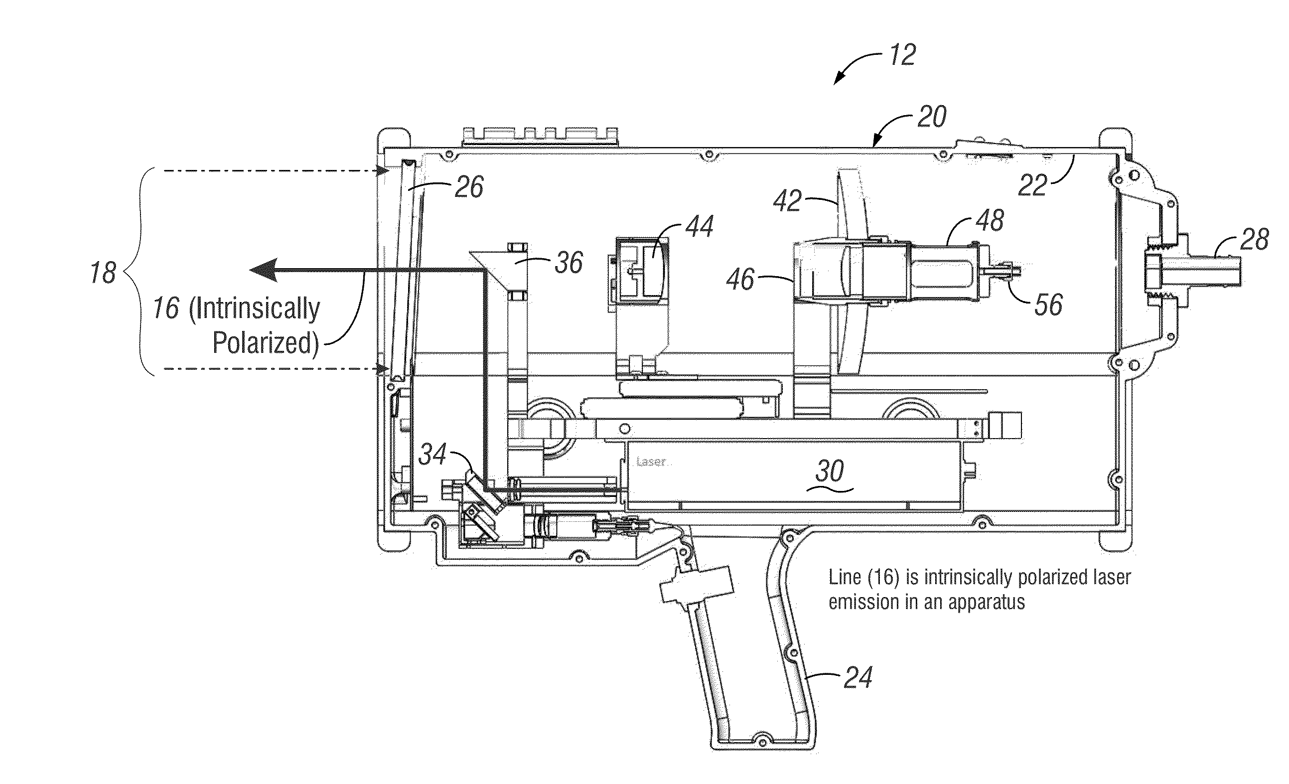
[0052]For a better understanding of the invention, specific forms or embodiments it can take will now be described in detail. Frequent reference will be taken to the accompanying drawings, which are itemized above. Reference numerals will be used to indicate certain parts or locations in the drawings. The same reference numerals will indicate the same parts or locations unless otherwise indicated.

[0053]These embodiments will focus upon stand-off distance detection of chemical substances with a portable detection system. However, it is to be understood that individual aspects could be implemented in different ways, at different distances, and for different applications.

[0054]The examples given are neither inclusive nor exclusive of all the forms and embodiments that aspects of the invention can take.

Method

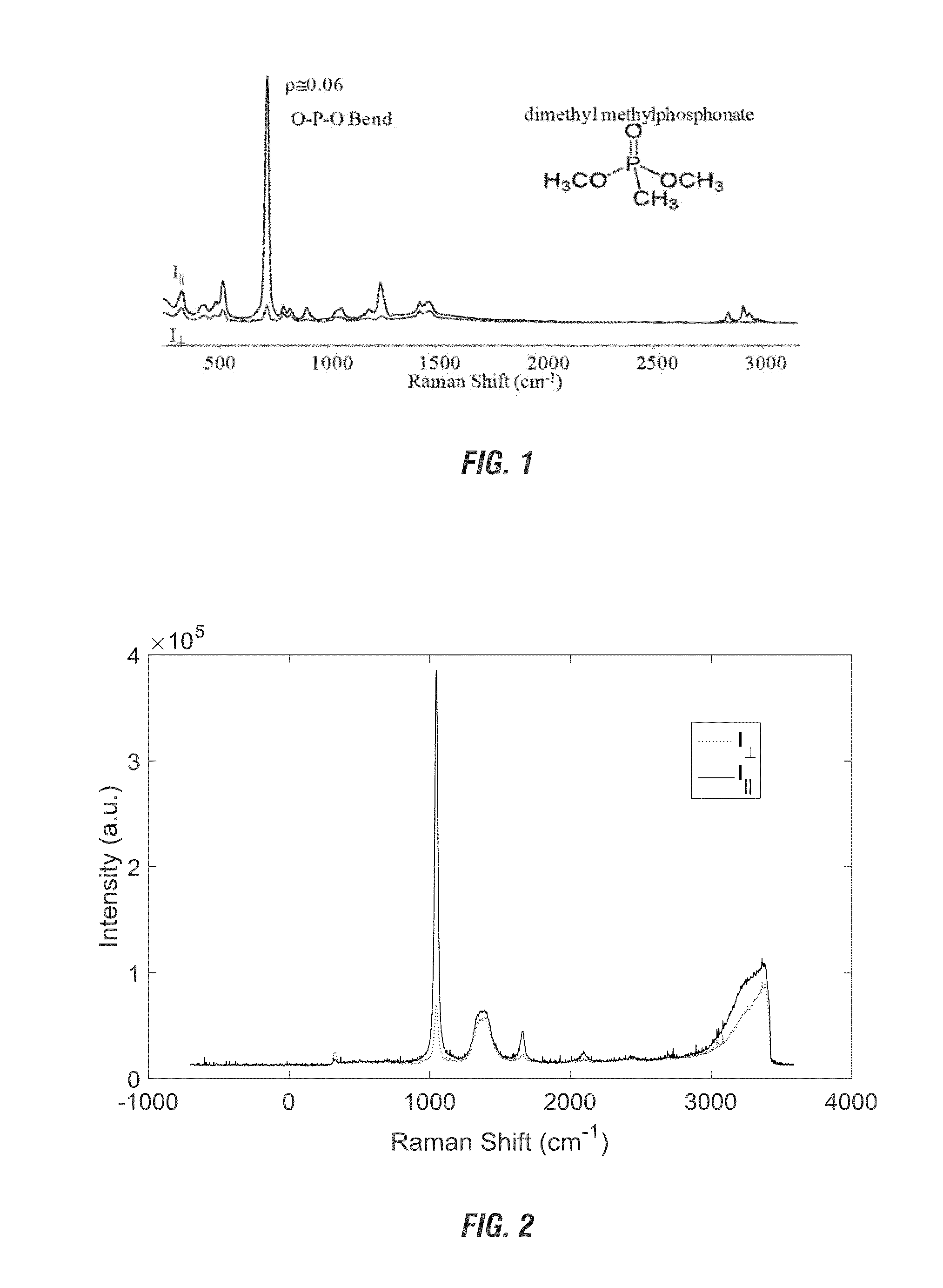
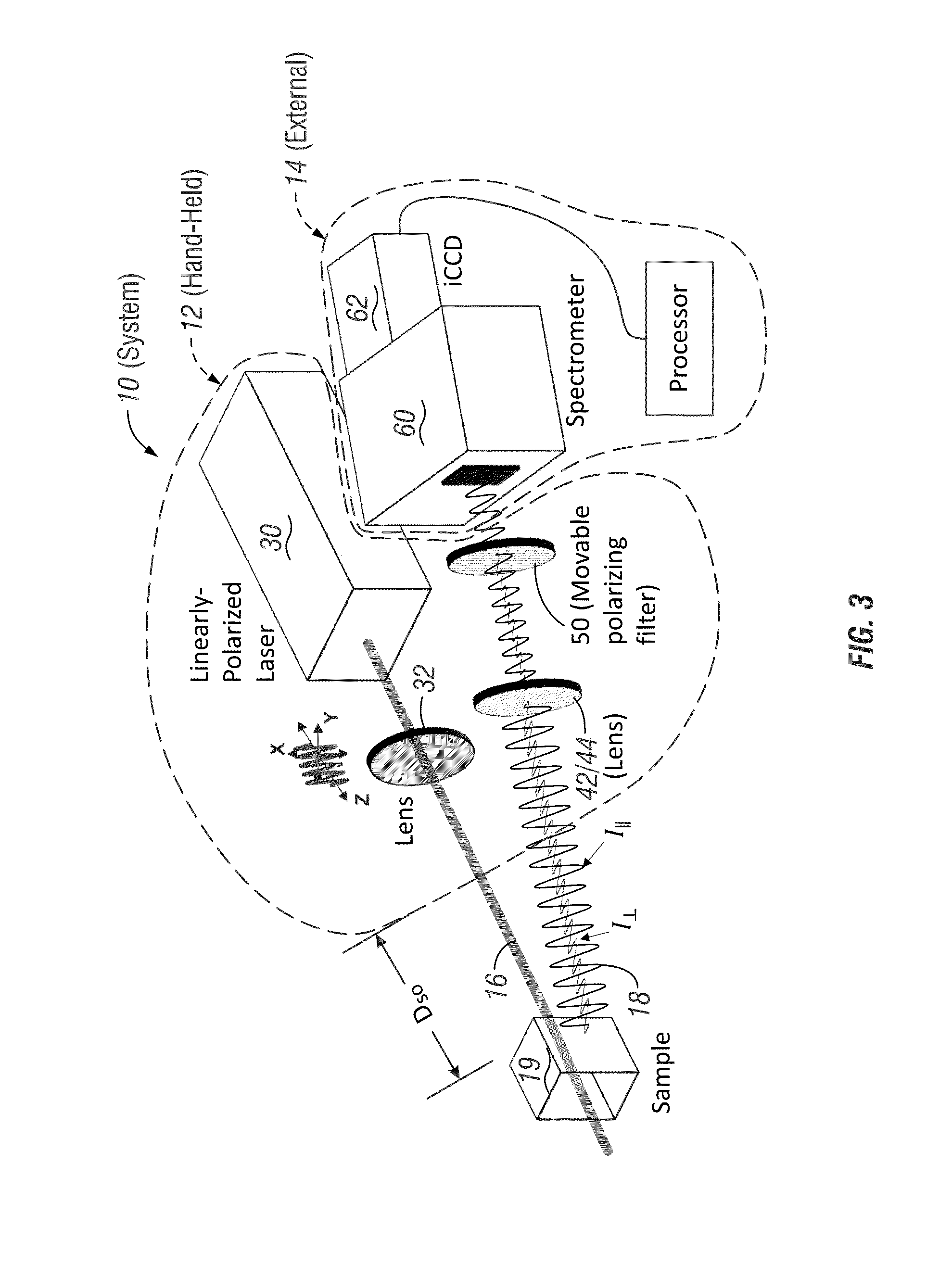
[0055]In one aspect or embodiment, the present invention seeks to remove fluorescence from a Raman spectrum collected at a standoff distance (see, e.g., diagrammatically ill...


PUM


Abstract

A method for utilizing polarization as a scheme for fluorescence removal from UV Raman spectra collected in a standoff detection scheme has been invented. In this scheme, a linearly polarized ultraviolet (UV) laser interacts with a material on a surface or in a container. The material generates Raman scattering with polarization contributions relative to that of the laser. The material possibly fluoresces as well, but the fluorescence is generally unpolarized. By subtracting a scaled version of the perpendicular component from the parallel component of the returned signal both relative to the laser source polarization—it is possible to generate a spectrum that is fluorescence free and contains the strongest features of the Raman scattered light.

Description

RELATED APPLICATIONS[0001]This application claims, under 35 U.S.C. §119 and / or §120, priority to and the benefit of provisional application U.S. Ser. No. 62 / 063,472 filed Oct. 14, 2014, which is incorporated by reference in its entirety herein.BACKGROUND OF THE INVENTION[0002]1. Field of the Invention[0003]The present invention relates to apparatus, systems, and techniques for processing a Raman scattering signal and, in particular, to distinguishing Raman spectra from fluorescence in Raman spectroscopy, including when the Raman spectra and fluorescence is generated by and detected at an instrument at standoff distances from a target material.[0004]2. Problems in the Art[0005]When applying Raman spectroscopy to the detection of explosives or toxic substances at standoff ranges (e.g. meters to tens of meters, and perhaps one hundred meters and possibly more), a chief drawback is the obscuring of the Raman scattering signal by fluorescence.[1,2] Fluorescence is generally excited whene...

Claims


Application Information

Patent Timeline
IPC IPC(8): G01N21/65G01N33/22
CPCG01N21/65G01N33/227G01N2201/0683G01N2201/121G01N2201/06113G01J2003/4424G01N2021/1793G01J3/0291G01J3/0237G01J3/28G01J3/44G01J3/0224G01J3/0262G01J3/0272
Inventor FORD, ALAN R.HOPKINS, ADAM J.
Owner ALAKAI DEFENSE SYST
Learn More