Method of Additive Manufacturing and Heat Treatment

a technology of additive manufacturing and heat treatment, which is applied in the direction of welding/cutting auxillary devices, non-electric welding apparatuses, auxiliary welding devices, etc., can solve the problems of not being able to withstand the temperature of heat treatment furnaces and being likely to have a very high thermal mass

Active Publication Date: 2016-04-21
AIRBUS OPERATIONS LTD
View PDF7 Cites 39 Cited by
  • Summary
  • Abstract
  • Description
  • Claims
  • Application Information

AI Technical Summary

Benefits of technology

[0017]Preferably the fixture has a mass which is less than ten times, preferably less than five times, and most preferably less than two times a collective mass of the substrate and the part. This makes it easy to transfer them between the additive manufacturing system and the heat treatment system. Where an attachment system is provided, then typically the fixture and attachment system have a collective mass which is less than ten times, preferably less than five times, and most preferably less than two times a collective mass of the substrate and the part.

Problems solved by technology

The bed in WO2014 / 072699 is not suited for heat treatment because: it is a heavy structure which is not suited to being moved easily from the additive manufacturing system; it may be too large to fit into a conventional heat treatment furnace; it may not be able to withstand the temperatures in a heat treatment furnace; and it is likely to have a very high thermal mass.

Method used


Image

  • Method of Additive Manufacturing and Heat Treatment
  • Method of Additive Manufacturing and Heat Treatment
  • Method of Additive Manufacturing and Heat Treatment

Examples


Embodiment Construction

)

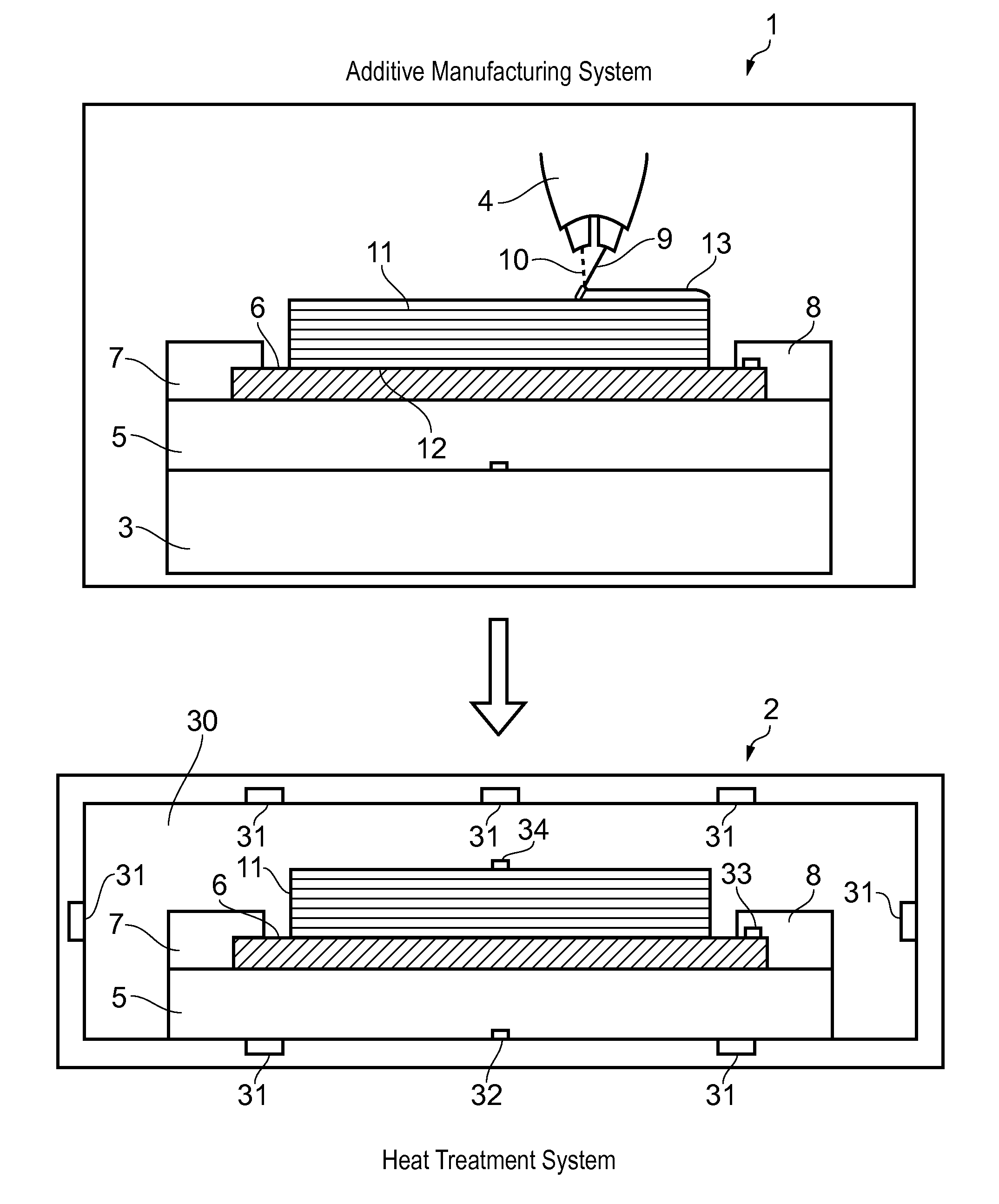
[0032]FIG. 1 shows an additive manufacturing system 1 and a heat treatment system 2. The additive manufacturing system 1 comprises a chamber containing a table 3 and a build head 4. A fixture 5 is shown in FIG. 1 on the table 3.

[0033]In a first step, a substrate 6 is placed on the fixture 5 and secured by clamps 7, 8. The substrate is pre-formed, in other words it is not formed by additive manufacturing on the fixture 5. Typically the substrate 6 is secured to the fixture 5 outside the chamber of the additive manufacturing system 1, and then the fixture 5 carrying the substrate 6 is introduced into the chamber and placed on the table 3.

[0034]In a second step, the build head 4 is operated to perform a build process by building a near net shape part 11 on the substrate 6 secured to the fixture 5. The build head 4 feeds metallic feedstock material 9 (such as titanium alloy or aluminium alloy) towards the substrate, and the material 9 is melted by a laser beam 10 as it is fed onto the ...


PUM

PropertyMeasurementUnit
temperaturesaaaaaaaaaa
temperatureaaaaaaaaaa

Abstract

A method of additive manufacturing and heat treatment. A substrate is secured to a fixture and an additive manufacturing system is operated to perform a build process by building a part on the substrate secured to the fixture, the part being built by forming a series of layers of metallic material on the substrate, the metallic material melting and solidifying during the build process thereby bonding the part to the substrate and creating thermally induced stress in the part. The part, the substrate and the fixture are moved together from the additive manufacturing system to a heat treatment system, wherein the substrate remains secured to the fixture and the part remains bonded to the substrate as they are moved. The heat treatment system is operated to perform a heat treatment process by heating the part, the substrate and the fixture together thereby relieving the thermally induced stress in the part, the substrate remaining secured to the fixture during the heat treatment process. Finally the substrate is released from the fixture and the part and the substrate are removed from the fixture. The part remains bonded to the support as they are removed from the fixture.

Description

FIELD OF THE INVENTION[0001]The present invention relates to a method and associated apparatus for additive manufacturing and heat treatment.BACKGROUND OF THE INVENTION[0002]Additive manufacturing typically involves the production of three-dimensional parts by depositing material layer by layer to build either complete components or add features to a pre-formed substrate. It contrasts with conventional subtractive machining processes, in that a component produced by an additive manufacturing process is near net shape, i.e. it is close to its final (net) shape thereby reducing the need for additional finishing and wasted excess material.[0003]A key challenge with additive manufacturing processes, particularly for the production of larger components, is the distortion of the manufactured part during the deposition process due to the high internal stresses generated as the deposited material solidifies.[0004]A solution to this problem is presented in WO2014 / 072699. A bed supports a par...

Claims


Application Information

Patent Timeline
Patent Type & Authority Applications(United States)
IPC IPC(8): C21D1/00B23K26/342
CPCC21D1/00B33Y10/00B23K26/342B23K37/0408B23K26/1476C21D9/50B23K26/702B23K26/082C21D2251/00B23K2103/10B23K2103/14Y02P10/25B22F10/64B22F12/90B22F10/28B22F10/25B22F12/30B23K5/18B23K9/04B23K10/027B23K11/0013B23K15/0086B23K20/1215B23K25/005C21D9/00B29C64/153B29C64/245B33Y40/20B29C64/188
Inventor MEYER, JONATHANHENSTRIDGE, ANDREW
Owner AIRBUS OPERATIONS LTD
Why Eureka
Try Eureka