Plunger lift arrangement

a technology for oil and gas wells and lifts, applied in the direction of fluid removal, borehole/well accessories, construction, etc., can solve the problems of reducing production flow, generating a further buildup of liquid, and losing production tim

a technology for oil and gas wells and lifts, applied in the direction of fluid removal, borehole/well accessories, construction, etc., can solve the problems of reducing production flow, generating a further buildup of liquid, and losing production tim

US20160108710A1Active Publication Date: 2016-04-21WELL MASTER CORP

Image

  • Plunger lift arrangement
  • Plunger lift arrangement
  • Plunger lift arrangement

Examples


Embodiment Construction

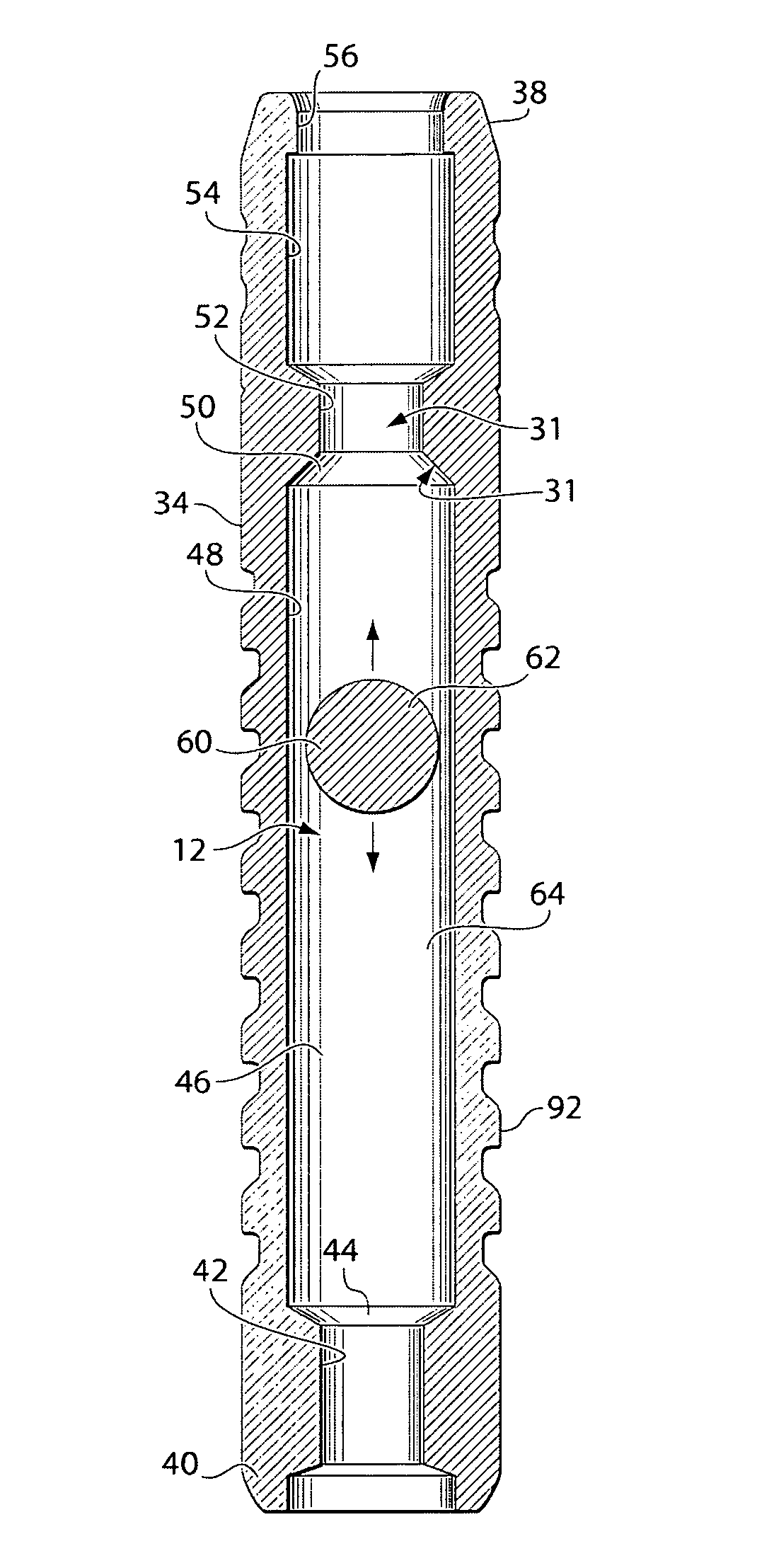
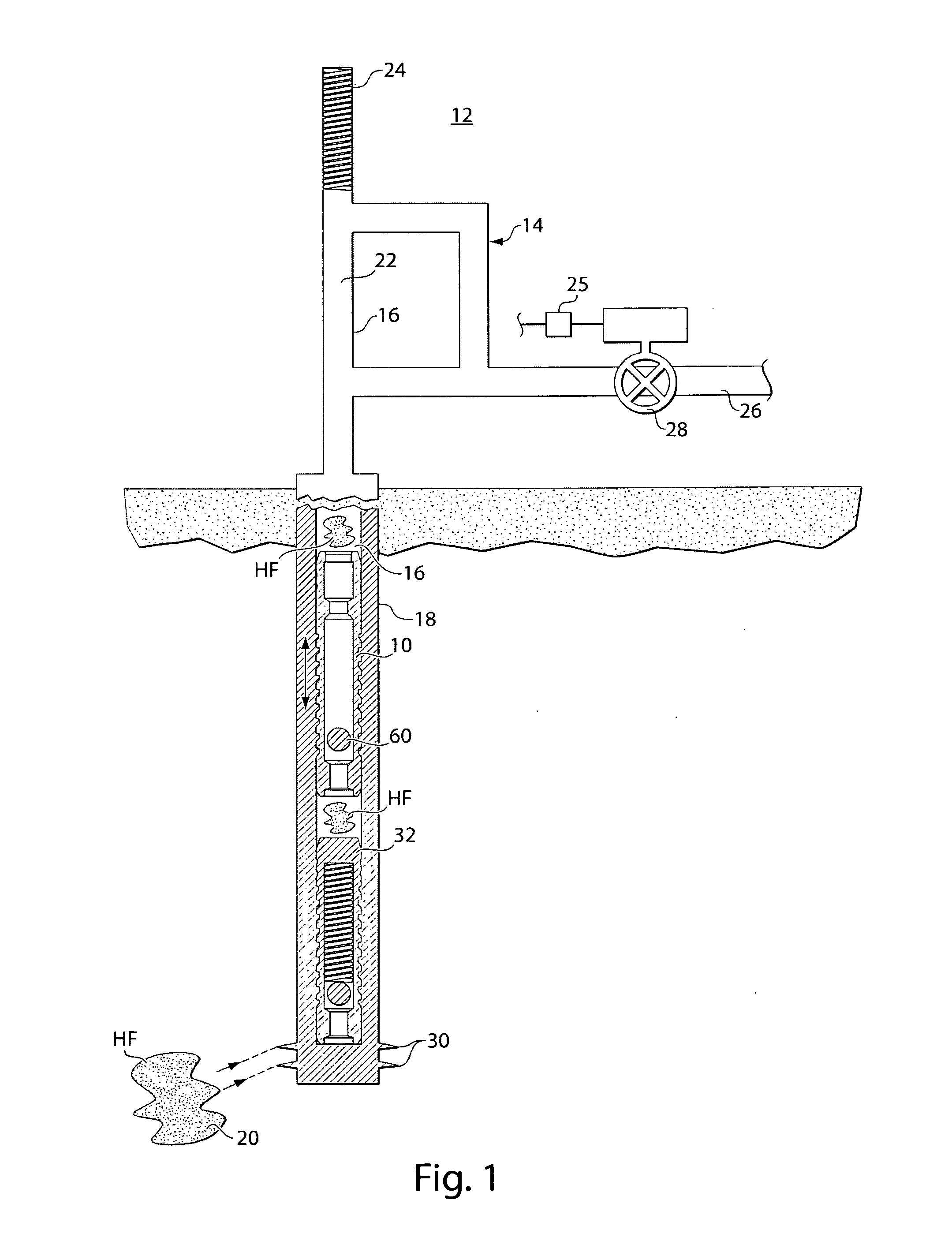
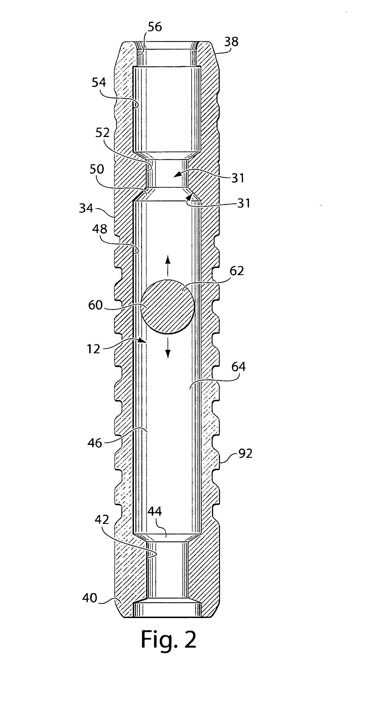
[0030]The present invention relates to a plunger / plunger assembly 10 which is utilized to travel within a gas or gassy oil well system 12 as represented in FIG. 1, to enable efficient recovery of liquids therefrom which would otherwise not normally have been captured. The gas well system 12 utilized in the present invention comprises an above ground wellhead complex 14 comprised of an inner tubing 16 which extends into the ground and is surrounded longitudinally by an outer casing 18 into the lower well formation 20 therebeneath. The above ground wellhead complex 14 comprises a system of conduits 22 for receiving and capturing the plunger 10 thereat by an upper impact damping spring 24 and a sales line 26 for withdrawal of collected hydrocarbon fluid which sales line 26 is controlled via a proper computerized fluid control circuit 25 through a meter valve 28 within that sales line 26. The inner tubing 16 extends from the ground level into the hydrocarbon formation 20 within the eart...


PUM


Abstract

A plunger for extraction of hydrocarbon fluids from a gas well system wherein the plunger is arranged to move upwardly and downwardly in an arrangement of inner tubing within the gas well system. The plunger comprises an elongated housing sleeve having a longitudinally directed bore, an elongated central chamber within the longitudinally directed bore, the central chamber having a plug nestable seat at each end thereof; and a plug displacably arranged within the central chamber so as to seal the bore during travel of the plug in a first direction in the inner tubing, and to permit flow of fluid through the plunger as the plunger travels in a second direction in the inner tubing.

Description

FIELD OF THE INVENTION[0001]This invention relates to plunger lift arrangements for oil and gas wells, and more particularly to improvements to assist the plunger in lifting fluids to the top of the well, and is a continuation-in-part of Ser. No. 13 / 999,272 filed on Feb. 4, 2014, which is a continuation-in-part of Ser. No. 13 / 506,464, filed on Apr. 20, 2012, which is a continuation-in-part application of Ser. No. 13 / 374,830, filed Jan. 17, 2012 and is a continuation-in-part application of Ser. No. 12 / 586,736, filed Sep. 25, 2009, now U.S. Pat. No. 8,201,629, issued 19 Jun. 2012, and of Ser. No. 12 / 460,099, now U.S. Pat. No. 8,162,053, issued 24 Apr. 2012, which is a re-filing of Ser. No. 12 / 313,279, and is a continuation-in-part application of Ser. No. 11 / 715,216, now U.S. Pat. No. 7,748,448, issued 6 Jul. 2010 and also of Ser. No. 12 / 217,756, now U.S. Pat. No. 7,793,728, issued 14 Sep. 2010, which is a continuation of Ser. No. 11 / 350,367, now U.S. Pat. No. 7,395,865 which was based...

Claims


Application Information

Patent Timeline
21 Apr 2016
Publication
US20160108710A1
IPC
E21B43/12; E21B34/08
CPC
E21B43/123; E21B2034/002; E21B34/08; E21B43/121
Inventors
HIGHTOWER, KEVIN W.; GREEN, DAVID A.