Rf/microwave high power switching combiner unit

Inactive Publication Date: 2016-04-21
DAICO IND
View PDF2 Cites 9 Cited by
  • Summary
  • Abstract
  • Description
  • Claims
  • Application Information

AI Technical Summary

Benefits of technology

The patent describes a switching combiner unit (SCU) that can combine RF or microwave outputs from multiple power amplifier units (PAUs). The SCU can switch between an on-line mode where the PAUs amplify the same RF or microwave input signal and deliver it to the output, and a standby or off-line mode where the PAUs do not amplify the same signal. The use of the SCU ensures that the output impedance remains constant regardless of changes in the number of on-line PAUs. The signal combining circuitry includes RF switches which control the signal flow between the input and output ports of the SCU based on control signals. The RF switches include diodes that shunt signals in the forward or reverse direction to facilitate the coherent summing of the outputs from all the on-line PAUs. The technical effects of this patent include improved signal quality, increased efficiency, and reduced interference in RF or microwave systems.

Problems solved by technology

However, these radar systems may provide a mean time between failures (MTBF) of only hundreds of hours.
This can be problematic in mission-critical applications, such as in radar on a military ship or in an airport control tower.
However, the power level and power density of SSHPAs may not be as great as the rival Klystron.
Reliability can also be a problem.
Thus, further increasing device unit power may not reliably achieve a needed high power.
However, it may not be sufficiently reliable for power levels greater than 100 kW.
The use of lower power devices in HPA may also create mechanical complications and may not have a needed power density.
This analysis may apply for ultra-long pulse, ultra-high duty cycle, and CW operation power amplifiers with lower output power, because significant junction temperature increases may dramatically decrease the reliability of HPA according to equations 2 and 3.
In general, RF and microwave SSHPAs utilizing conventional combining architecture summing up multiple solid state power devices can face ultra-high power and ultra-high power density challenges in comparison to rival technologies due to limitations in power device availability and / or reliability.

Method used


Image

  • Rf/microwave high power switching combiner unit
  • Rf/microwave high power switching combiner unit
  • Rf/microwave high power switching combiner unit

Examples


Embodiment Construction

[0067]Illustrative embodiments are now described. Other embodiments may be used in addition or instead. Details that may be apparent or unnecessary may be omitted to save space or for a more effective presentation. Some embodiments may be practiced with additional components or steps and / or without all of the components or steps that are described.

[0068]The following abbreviations are used in this disclosure:

[0069]Ao Operation availability

[0070]BAM Basic amplifier module

[0071]OAF Canadian Air Force

[0072]COM Combiner

[0073]CHPA Combined high power amplifier

[0074]DAU Driver amplifier unit

[0075]DIV Divider

[0076]DSCU Divider switching combiner unit

[0077]HPA High power amplifier

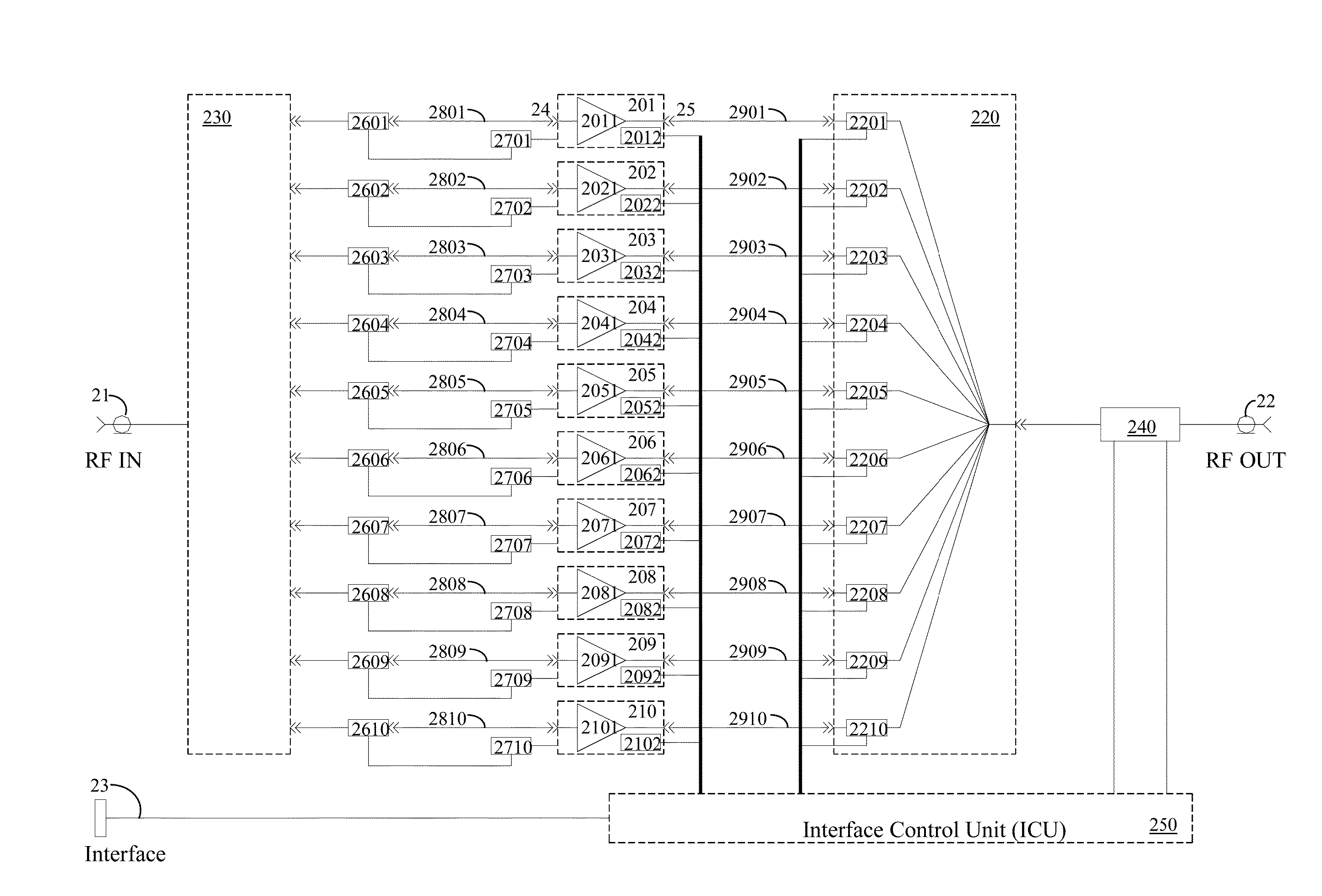
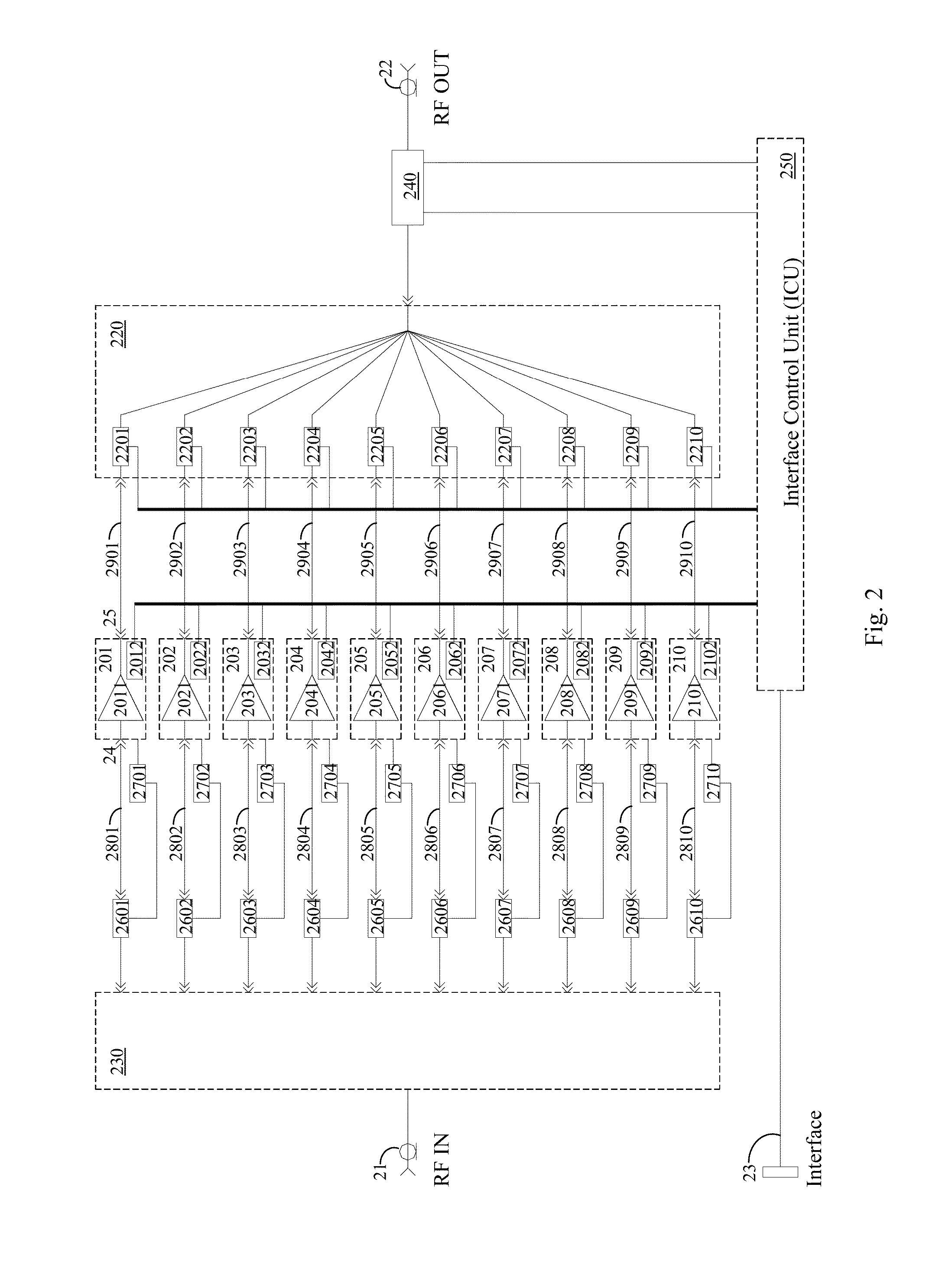
[0078]ICU Interface control unit

[0079]ICM Interface control module

[0080]IDD Input driver divider

[0081]IDDM Input Driver and Divider Module

[0082]LRU Line replaceable units

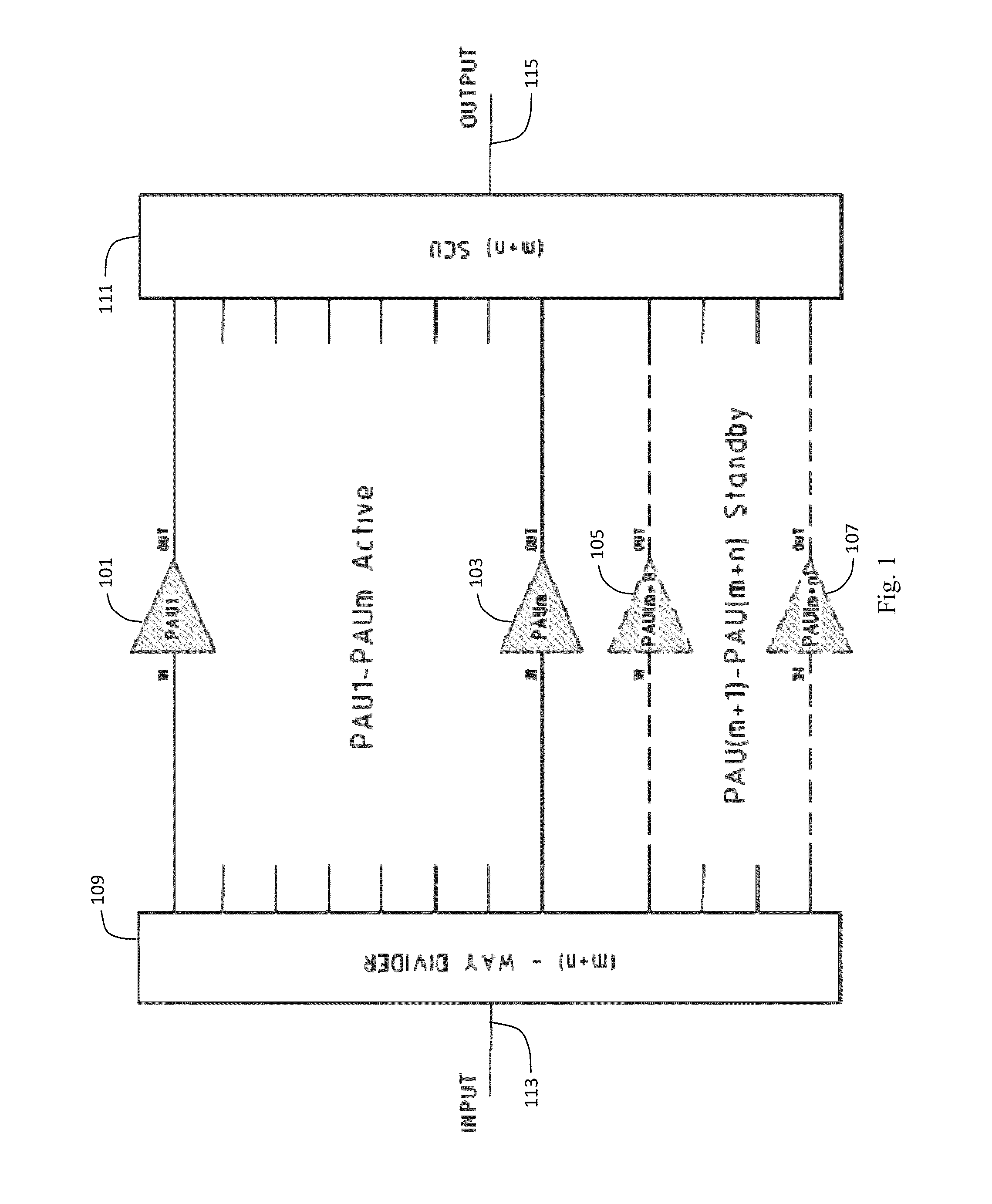
[0083]m Normally online LRUs

[0084]n Normally standby LRUs

[0085]MTBCF Mean time between critical failures

[0086]MTBF Mean time between failures

[0087...


PUM

PropertyMeasurementUnit
Flow rateaaaaaaaaaa
Wavelengthaaaaaaaaaa
Electric impedanceaaaaaaaaaa

Abstract

A switching combiner unit (SCU) may combine coherent RF or microwave outputs from multiple power amplifier units (PAUs). Each SCU may be able to be switched between an on-line mode (on-line PAU), during which the PAU amplifies a coherent instance of the same RF or microwave input signal and delivers that amplified input signal to an output, and a standby or off-line mode (standby / off-line PAU), during which the PAU does not amplify an instance of the same RF or microwave input signal or deliver an amplified input signal to the output. The SCU may include an input port that connects to each of the PAU outputs; a control signal input that receives one or more control signals that indicate whether each PAU is in the on-line or standby / off-line mode; signal combining circuitry that coherently sums the outputs from all of the on-line PAUs, while simultaneously isolating the standby / off-line PAUs from the output of the SCU and the outputs of the on-line PAUs; and an SCU output port that delivers the coherently summed outputs from all of the on-line PAUs.

Description

CROSS-REFERENCE TO RELATED APPLICATIONS[0001]This application is based upon and claims priority to U.S. provisional patent application 62 / 065,390, entitled “HIGH POWER DENSITY RF / MICROWAVE SOLID STATE POWER AMPLIFIER ARCHITECTURE,” filed Oct. 17, 2014, attorney docket number 094249-0011, and U.S. provisional patent application 62 / 096,811, entitled “ULTRA HIGH POWER SOLID STATE (M+N) REDUNDANT CHPA ARCHITECTURE,” filed Dec. 24, 2014, attorney docket number 094249-0012. The entire content of both of these applications is incorporated herein by reference.BACKGROUND[0002]1. Technical Field[0003]This disclosure relates to high power, solid state amplifiers for radio frequency and microwave signals, including pulse and CW radar signals.[0004]2. Description of Related Art[0005]RF and microwave power amplifiers may need to operate under pulsed conditions, such as in civilian and military radar systems. They may need to provide a high peak power to gain surveillance / transmit distance capacit...

Claims


Application Information

Patent Timeline
IPC IPC(8): H03F3/21
CPCH03F2203/21145H03F3/211H03F1/0277H03F3/195H03F3/602H01P5/16H01L2924/0002H05K7/20636H05K7/20645H05K7/209H05K7/20927H01L23/473H03F2200/447H03F2200/451H03F2203/21142H03F1/0211H03F2203/21106H03F1/526H01L2924/00H01L23/373H03F1/0205H03F3/19H03F3/68H03H7/383H03F1/0222A61K48/00H05K7/20
Inventor BLAIR, EDDIE
Owner DAICO IND
Why Eureka
Try Eureka