
Radiotherapy apparatus

a radiotherapy and apparatus technology, applied in the direction of material analysis, wave/particle radiation therapy, instruments, etc., can solve the problem of not verifying the actual dose that is delivered to the patien

Active Publication Date: 2016-04-28
ELEKTA AB
View PDF3 Cites 12 Cited by
  • Summary
  • Abstract
  • Description
  • Claims
  • Application Information

AI Technical Summary

Benefits of technology

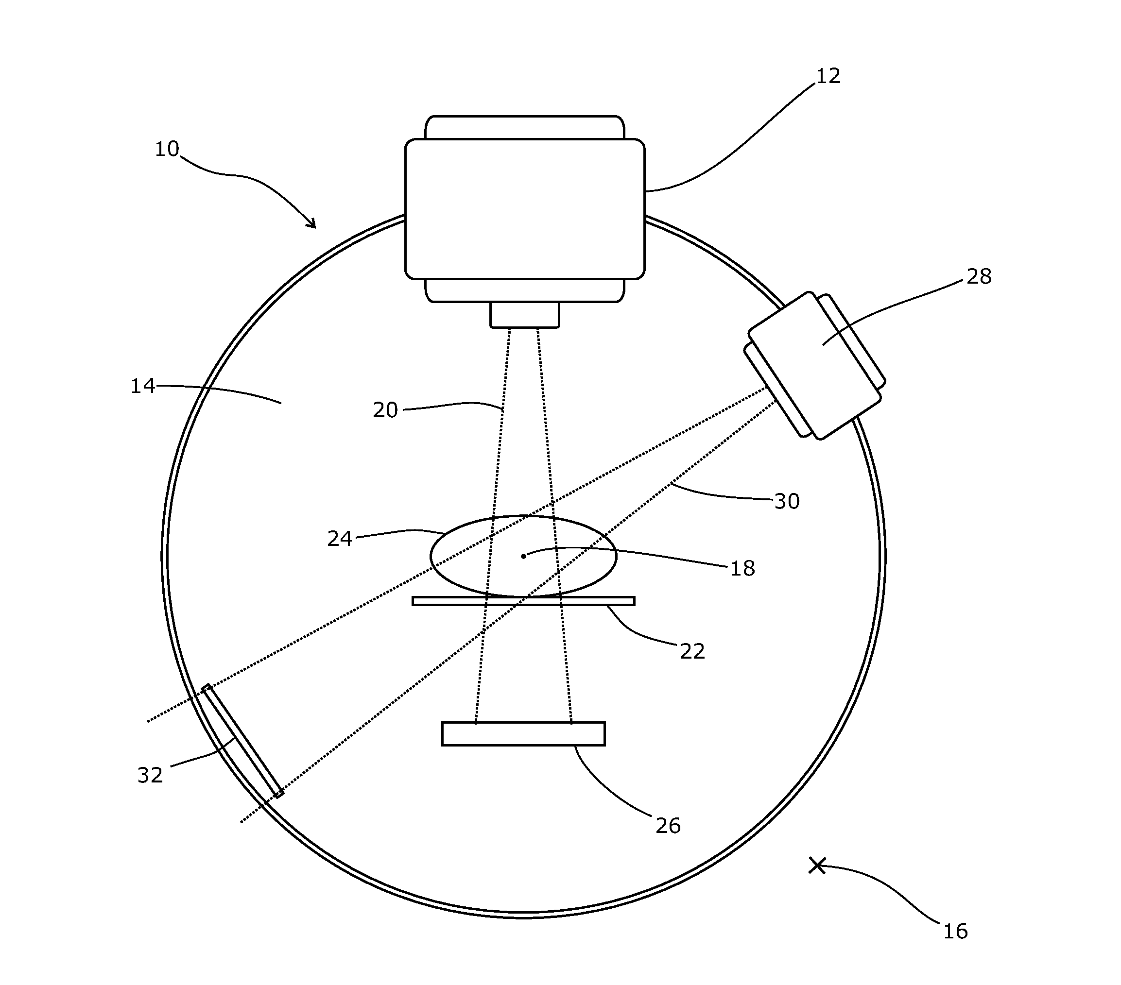
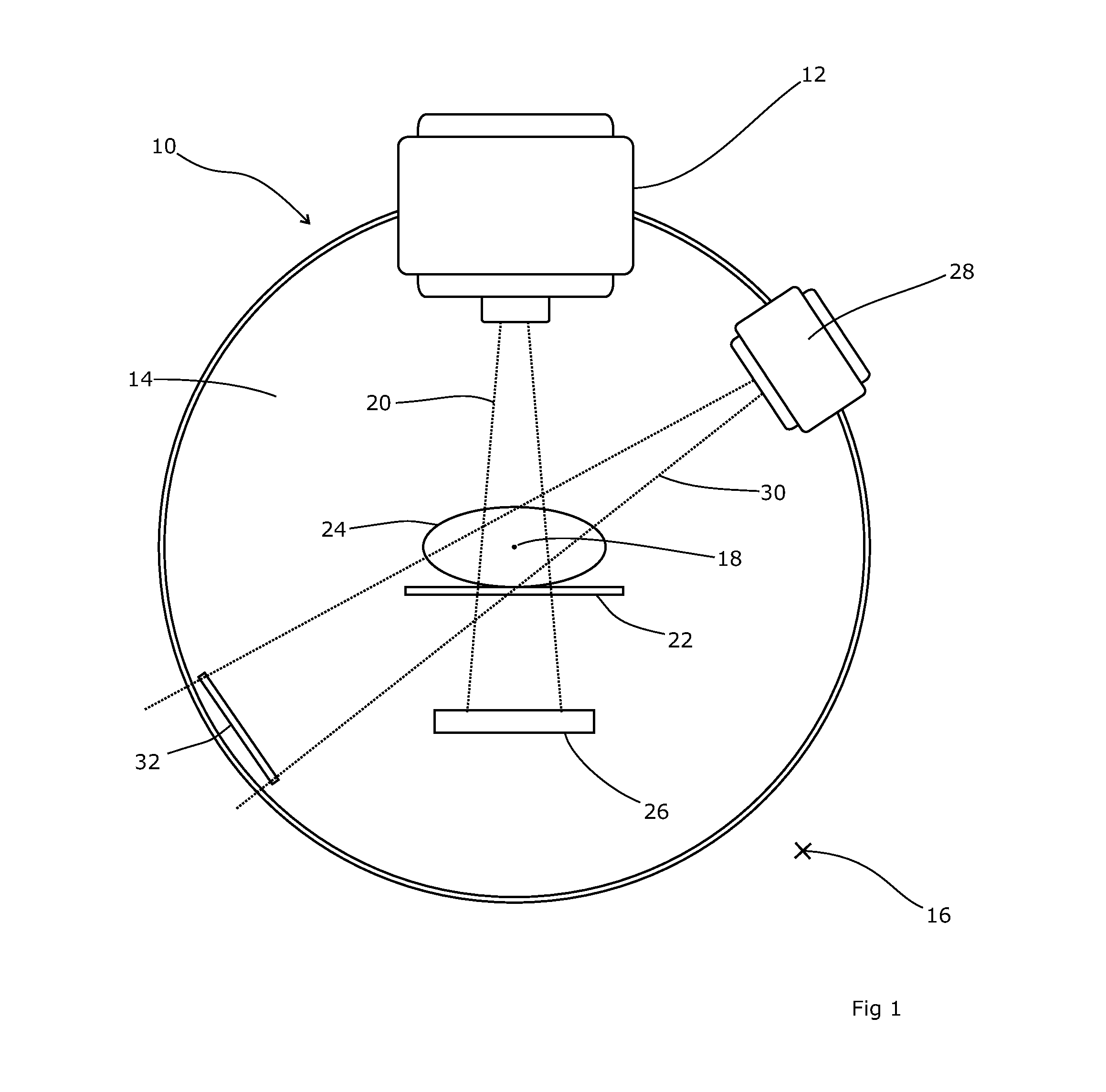
The patent describes a system where a portal image is combined with a better-quality background image for better visualization. This is particularly useful for clinicians reviewing treatment results. The system uses a rotating gantry with two sources that can be positioned around the patient to treat the lesion from multiple directions and minimize dose to healthy tissue. The image from the second detector is obtained at a different time from the image from the first detector, and can be timed to gantry rotation to minimize blurring.

Problems solved by technology

Whilst the arrangement of US2010 / 0119032A1 ensures that the dose is displayed against an up-to-date image of the patient anatomy, it does not verify the actual dose that is delivered to the patient.

Method used


Image

  • Radiotherapy apparatus
  • Radiotherapy apparatus
  • Radiotherapy apparatus

Examples


Embodiment Construction

[0021]Referring to FIG. 1, a radiotherapy apparatus 10 includes a therapeutic source 12 which is mounted on a rotateable gantry 14. The gantry 14 is in the general form of a horizontally-arranged cylinder, set into a wall structure 16 and rotatable around the axis 18 of the cylinder, thus carrying the therapeutic source 12 with it as it rotates. The therapeutic source 12 is mounted on the end of an arm projecting from the gantry 14; the source usually comprises a linear accelerator which can be located within the arm and the gantry, with its output directed towards an x-ray target in the head section 12 to produce a beam of x-rays with an energy of about 1-5 MeV. If clinically required, the x-ray target can moved out of position to allow therapeutic use of the electron beam produced by the linear accelerator instead.

[0022]The arm and head section 12 are mounted on the gantry 14 offset from the axis 18 and with the therapeutic source 12 oriented towards the axis 18, so that the centr...


PUM


Abstract

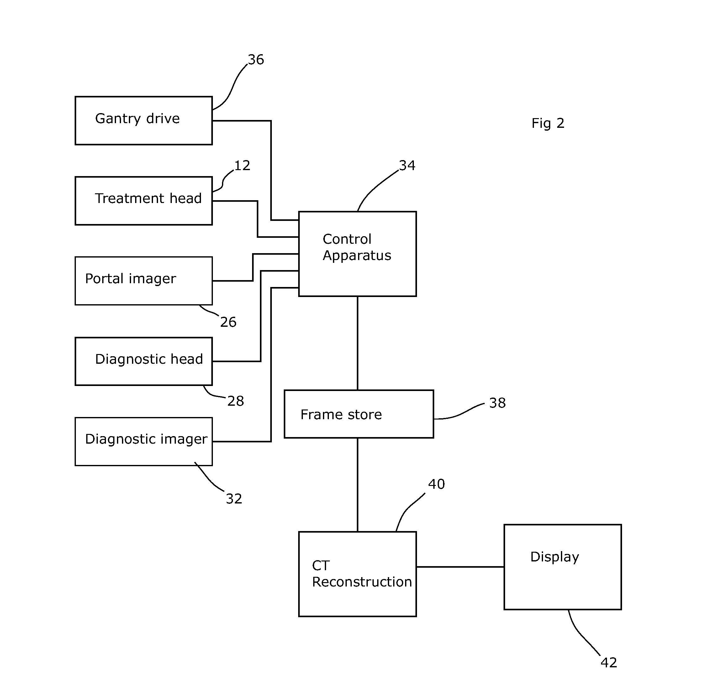
We disclose a radiotherapy apparatus with a dose verification system in which the portal image is displayed against a background of a better-quality image diagnostic image, such as a two-dimensional radiograph, an ultrasound image, or a section taken from a three-dimensional magnetic-resonance image, cone-beam CT image, or the like.

Description

FIELD OF THE INVENTION[0001]The present invention relates to apparatus for delivering radiotherapy.BACKGROUND ART[0002]Radiotherapy consists of the application of harmful radiation to lesions (such as tumours) within the body. The radiation interferes with cellular processes within the lesion and alleviates the condition. Typically, the radiation takes the form of high-energy beams of x-radiation, with photon energies usually in excess of 1 MeV.[0003]A number of systems are provided for monitoring the radiation that is delivered, including a so-called “portal” image, which is an image created by the treatment beam, captured using a flat-panel detector after the beam has passed through and been attenuated by the patient.[0004]However, portal images are usually of a relatively low quality, with poor contrast within soft tissue areas. This is inherent to portal imaging, since the attenuation coefficients of the materials involved are very similar at the x-ray energies used for the trea...

Claims


Application Information

Patent Timeline
IPC IPC(8): A61N5/10
CPCA61N5/1049A61N2005/1058A61N2005/1055A61N5/1071A61N2005/1054A61N2005/1061A61N2005/1072
Inventor SANKEY, STEPHEN
Owner ELEKTA AB
Learn More