Mirror mounting, alignment, and scanning mechanism and scanning method for radiographic X-ray imaging, and X-ray imaging device having same

a radiographic x-ray and mirror technology, applied in the field of imaging systems, can solve the problems of large displacement error, single mirror yielding only a thin fan-beam of mono-energetic x-ray light, etc., and achieve the effect of reducing scattering

Inactive Publication Date: 2011-07-12
REFLECTIVE X RAY OPTICS
View PDF11 Cites 9 Cited by
  • Summary
  • Abstract
  • Description
  • Claims
  • Application Information

AI Technical Summary

Benefits of technology

[0010]The present invention includes a mounting, alignment, and scanning mechanism for grazing incidence X-ray mirrors used in conjunction with point-source X-ray tube. The invention includes (a) a 5-axis adjustable mirror mount, (b) a computer-controlled mirror scanner that is synchronized with the X-ray generator, (c) a two-axis adjustment mechanism for precisely positioning the scan axis relative to the X-ray focal spot, (d) a moving entrance grid that can be precisely positioned relative to an X-ray mirror stack in order to select which mirrors are used for an individual X-ray exposure, and (e) a scanning anti-scatter grid, having an attenuating slotted plate that is matched to the illumination pattern as defined by the specific mirror configuration. The scanning anti-scatter grid is used to minimize scattering in one direction. The present invention is aimed specifically at mammographic applications, however it can apply equally well to all other medical and industrial radiographic X-ray imaging applications.
[0015]Optionally, the mirror scanner may be operable at a selectively variable speed to thereby enable selective control of the scanning speed of the mirror. By controlling both the scanning speed of the mirror (e.g., the rate at which the linear motor drive pushes the optics bracket) and the position of the entrance grid aperture, the invention provides unrestricted control over X-ray intensity and energy, respectively, as a function of position in the image plane.
[0018]The inventive X-ray imaging device may optionally allow the mirror scanner to be operable at a selectively variable speed to thereby enable selective control of the scanning speed of the mirror. A slower scanning speed over a specific region of the item to be imaged corresponds to a greater exposure of X-rays in that region, while a faster scanning speed corresponds to a lesser exposure of X-rays. By controlling the X-ray exposure as a function of position, the image quality can be optimized, and in the case of medical imaging the patient dose can be minimized, for each specific item to be imaged.
[0019]In another aspect of the invention, the invention is an X-ray imaging device having a point-source X-ray tube which has a focal spot. A plurality of multilayer X-ray mirrors are rigidly secured to one another in a mirror stack, the mirror stack including a first plurality of multilayer mirrors adapted to reflect X-rays of a first energy and a second plurality of multilayer mirrors adapted to reflect X-rays of a second energy. A scannable mirror mount is provided upon which the mirror stack is mounted, the mirror mount alignable with the focal spot. A movable attenuation plate having at least one window is provided, disposed either one of i) interposed between the X-ray tube and the mirror stack or ii) interposed between the mirror stack and the item to be imaged. The window selectively allows at least one of the pluralities of mirrors to transmit X-rays of at least one corresponding energy to the item to be imaged, and the rest of the attenuation plate blocks at least another of the pluralities of mirrors from transmitting X-rays of at least one different corresponding energy, thereby enabling selection of at least one X-ray energy to be transmitted for imaging.
[0023]The mirror stack is preferably mounted on a mirror mount pivotable about a scanning axis alignable with a focal spot of the X-ray source. In this case, the inventive method includes the step of rotating the mirror mount about the scanning axis while maintaining alignment of the scanning axis with the X-ray focal spot. Optionally, the inventive method further includes the step of varying the speed of rotation of the mirror mount about the scanning axis to thereby enable selective control of the scanning speed of the mirror. By utilizing the speed varying step and the attenuation plate moving step, the inventive method enables control of X-ray intensity and energy-, respectively, as a function of position with respect to an item to be imaged.

Problems solved by technology

Because the mirrors only work at shallow grazing incidence angles, a single mirror will only yield a thin fan-beam of mono-energetic X-ray light.
For other imaging applications, this displacement error may be larger or smaller.

Method used


Image

  • Mirror mounting, alignment, and scanning mechanism and scanning method for radiographic X-ray imaging, and X-ray imaging device having same
  • Mirror mounting, alignment, and scanning mechanism and scanning method for radiographic X-ray imaging, and X-ray imaging device having same
  • Mirror mounting, alignment, and scanning mechanism and scanning method for radiographic X-ray imaging, and X-ray imaging device having same

Examples


Embodiment Construction

[0031]Description of the invention will now be given with reference to FIGS. 2-7. It should be understood that these figures are exemplary in nature and in no way serve to limit the scope of the invention, which is defined by the claims appearing hereinbelow.

[0032]A traditional radiographic X-ray imaging system has a point-source X-ray tube and an X-ray-sensitive imaging detector (either film / screen or digital): X-ray photons emitted from the focal spot pass through the tissue or sample under study where they are attenuated by an amount that depends on the composition and density of the sample. The resultant image is thus an attenuation map of the sample, integrated along the direction of X-ray propagation.

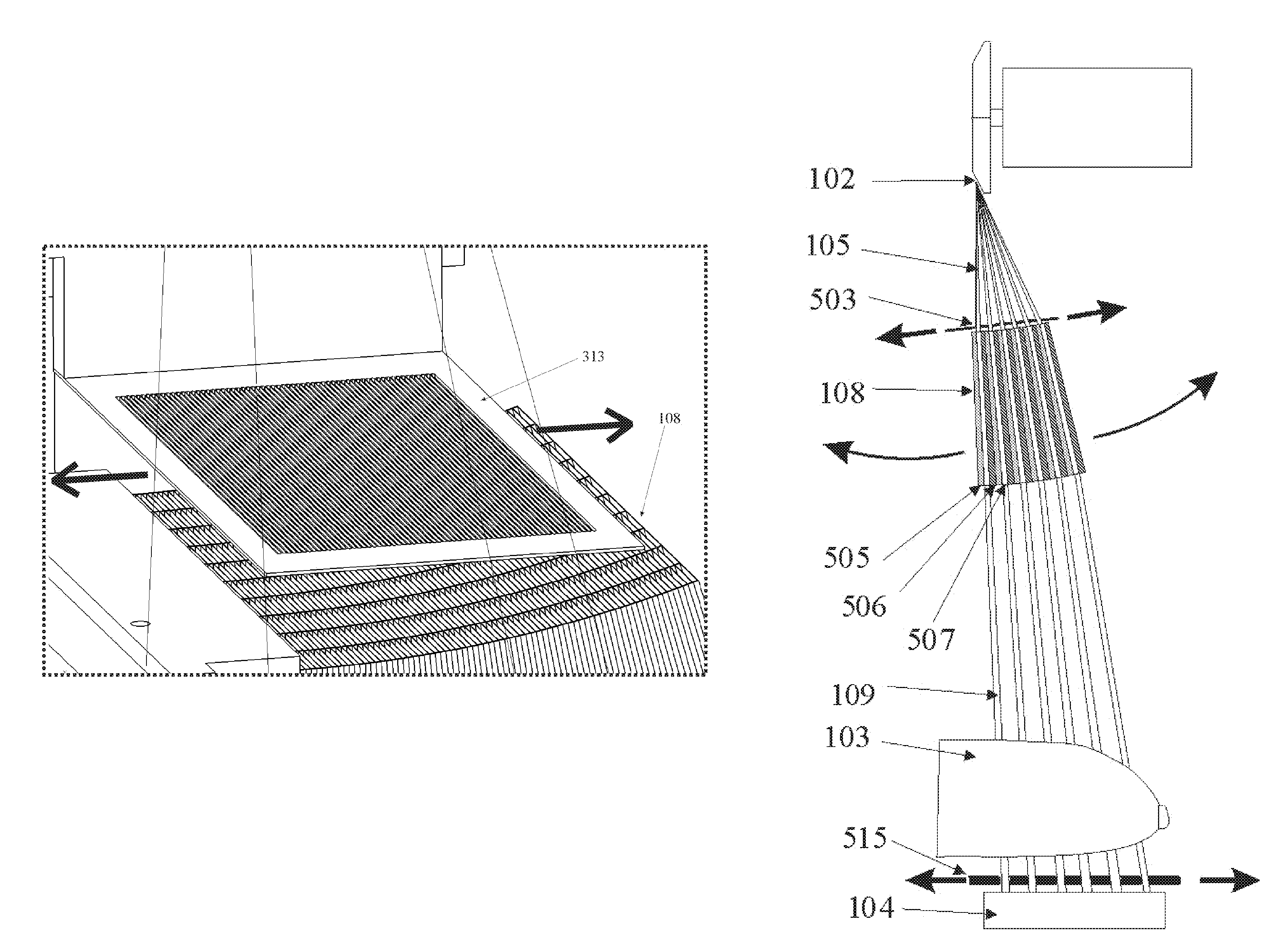
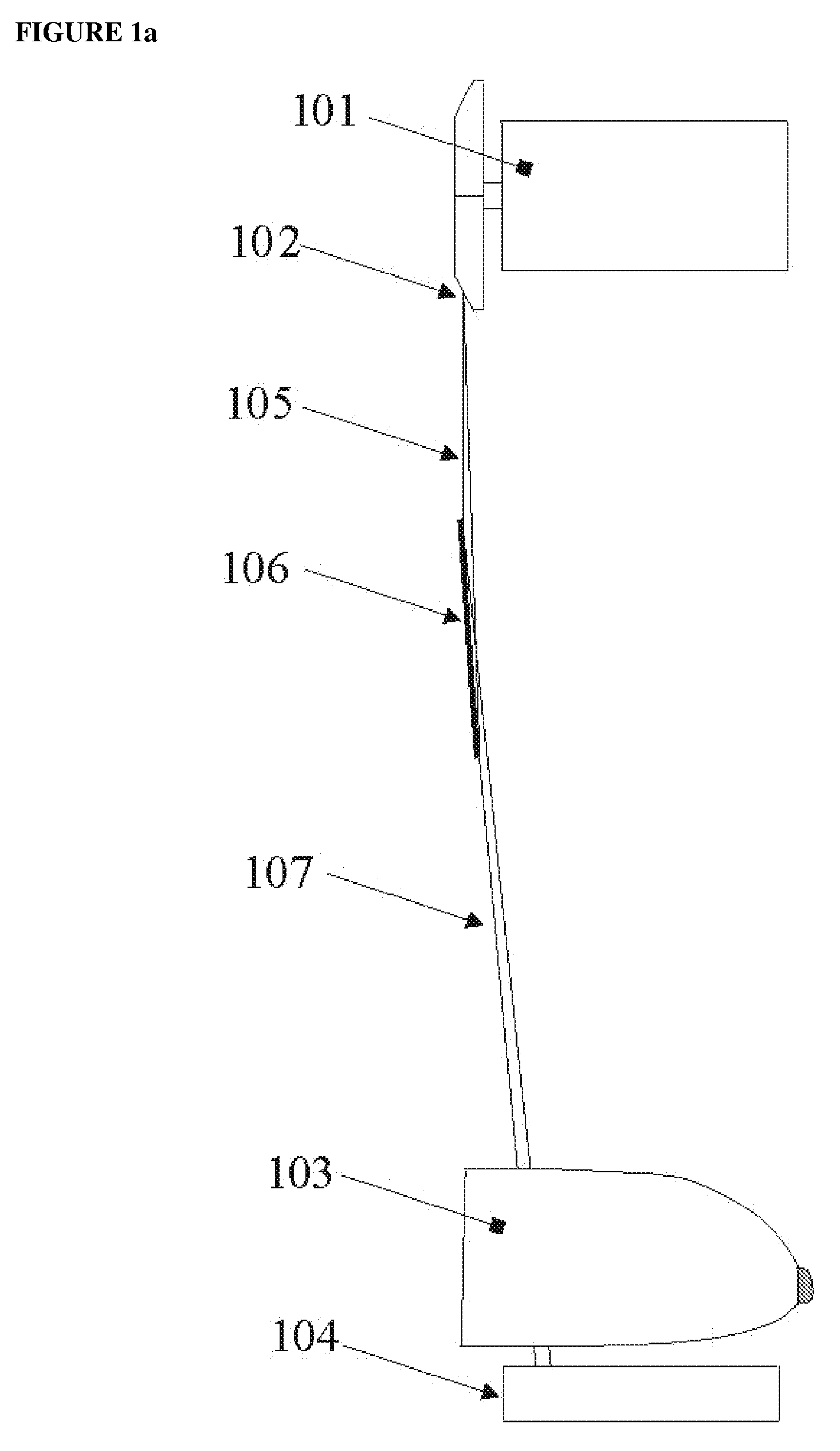
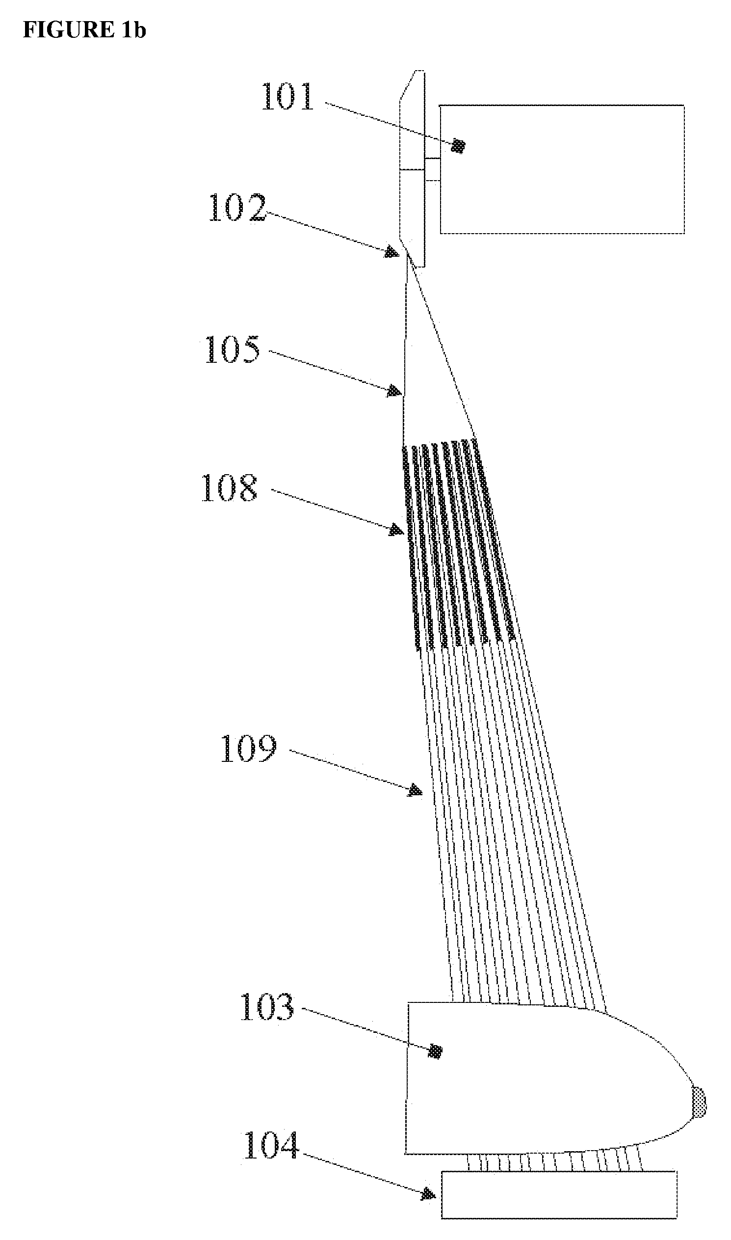
[0033]For many applications, increased signal contrast (and lower dose, for medical applications) can be obtained using mono-energetic X-rays, as produced, for example, by graded, periodic multilayer X-ray mirrors. One configuration utilizing X-ray mirrors is shown in FIG. 1a, in ...


PUM


Abstract

An X-ray imaging device and alignment / scanning system include at least one multilayer X-ray mirror mounted on a multi-axis adjustable mirror mount pivotable about a scanning axis. A mirror scanner is coupled with the mirror mount and synchronized with the X-ray source so that the mirror scanner moves the mirror mount about the scanning axis. The invention may include a plurality of mirrors, optionally in a stack, and preferably including first and second mirrors respectively adapted to reflect X-rays of first and second energies. A movable attenuation plate having a window selectively allows X-rays to be transmitted by one of the mirrors and blocks X-rays from the other mirror(s). Sets of the mirrors may be configured in blocks or interspersed. The mirror scanner may be operable at variable speeds to enable selective control of the scanning speed of the mirror.

Description

RELATED APPLICATIONS[0001]Domestic priority is claimed from U.S. Provisional Patent Application No. 61 / 062,918, filed Jan. 30, 2008, entitled “Mirror Mounting, Alignment, and Scanning Mechanism, and Scanning Method, for Radiographic X-ray Imaging”, the entirety of which is incorporated by reference herein.BACKGROUND OF THE INVENTION[0002]1. Field of the Invention[0003]The invention is directed to imaging systems, and more particularly to radiographic X-ray imaging systems, for medical, industrial, and other applications.[0004]2. Description of Related Art[0005]Radiographic X-ray imaging systems for medical, industrial and other applications typically use a point-source X-ray tube in which energetic electrons impinge upon a solid metal target thereby producing a cone-beam of X-ray light emanating from the focal spot. The spectrum of X-rays emitted from such tubes is poly-energetic, having line emission characteristic of the anode material used in the tube (commonly tungsten, or in th...

Claims


Application Information

Patent Timeline
Patent Type & Authority Patents(United States)
IPC IPC(8): G21K1/06G02B5/08G02B7/182
CPCA61B6/4021A61B6/482A61B6/502A61B6/5282G21K1/025A61B6/4291A61B6/032A61B6/4085
Inventor WINDT, DAVID L.
Owner REFLECTIVE X RAY OPTICS
Why Eureka
Try Eureka