X-ray detector

a detector and x-ray technology, applied in the field of x-ray detectors, can solve the problems of low sensitivity, limited use of photoconductor as a photoconductor, and high application voltage, and achieve the effects of low cost, easy manufacturing, and superior deposition properties on the substra

Active Publication Date: 2018-08-23
RAYENCE +1
View PDF0 Cites 8 Cited by
  • Summary
  • Abstract
  • Description
  • Claims
  • Application Information

AI Technical Summary

Benefits of technology

[0028]According to the present invention, a perovskite material has properties suitable for use as a photoconductor for an X-ray detector, and moreover, is inexpensive, can exhibit superior deposition properties on a substrate, and is easy to manufacture. Thereby, mass production of an X-ray detector at low cost within a short processing time can become possible.
[0029]In addition to the perovskite material, a quantum dot material for converting X-rays having specific energy into visible light is used, thus absorbing X-rays in a wide energy range from substantially low energy to high energy, thereby minimizing the dose of radiation poisoning to a patient and obtaining an image having high resolution and low noise.

Problems solved by technology

In this way, a direct-conversion-type detector is able to detect an electrical signal directly converted from X-rays, thus exhibiting high resolution, conversion efficiency and collection efficiency to thereby reduce radiation poisoning, but is currently problematic because of difficulty in commercialization.
a-Se suffers from high application voltage, low sensitivity and a charge-trapping phenomenon, and thus the use thereof as a photoconductor is limited.
Furthermore, CdTe, HgI2, PbI2 and PbO are disadvantageous because of complicated processing and high price, make it difficult to manufacture a large-area detector, and require a long period of time to realize mass production, and techniques for reproducible fabrication are currently insufficient.

Method used


Image

  • X-ray detector
  • X-ray detector
  • X-ray detector

Examples


first embodiment

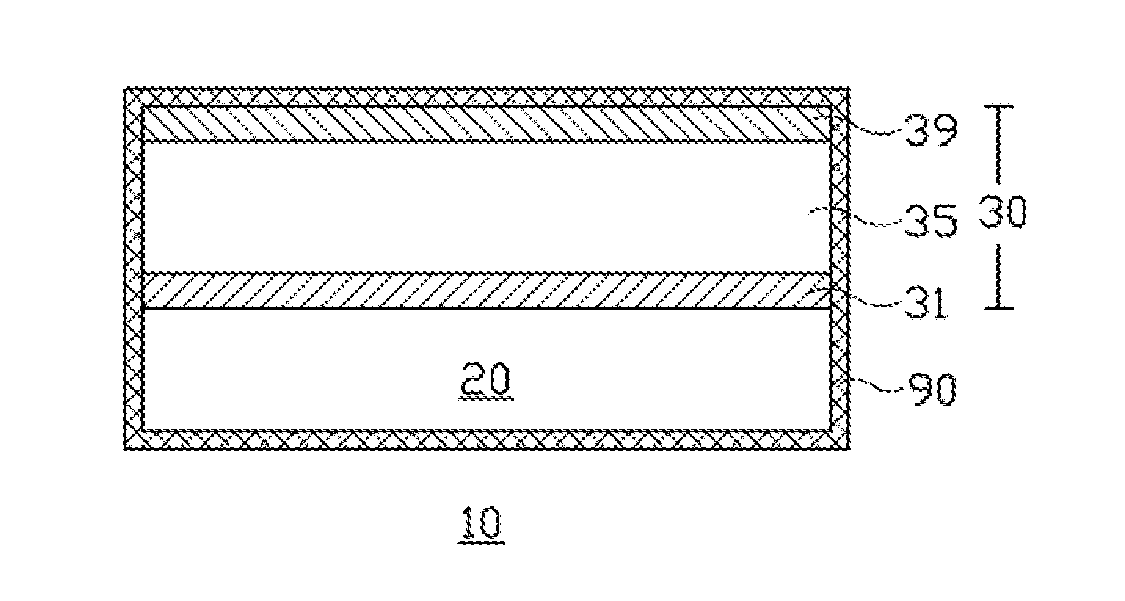
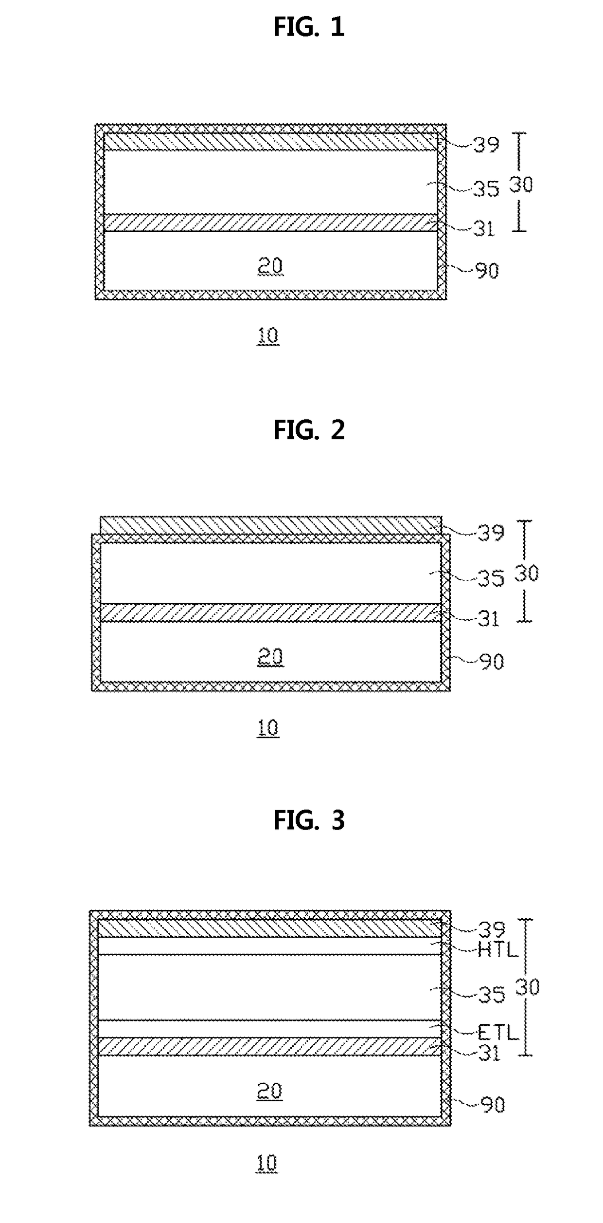
[0033]A direct-conversion-type X-ray detector according to a first embodiment of the present invention includes a perovskite material serving as a photoconductor.

[0034]Perovskite, having a crystal structure represented by the chemical formula ABX3, is known to be a special material that exhibits the properties of all of a non-conductor, a semiconductor, a conductor, and even a superconductor. In this embodiment, such a perovskite material is used as the photoconductor.

[0035]Here, the perovskite material used in the present embodiment is specified, and materials that constitute ABX3 are as follows.

[0036]A: an organic material, examples of which include methyl ammonium (CH3NH3) and formamidinium (NH2CH═NH2), or an inorganic material, an example of which includes cesium (Cs);

[0037]B: a metal material, examples of which include divalent transition metals, such as Pb, Sn, Cu, Ni, Bi, Co, Fe, Mn, Cr, Cd, Ge, Yb, and the like;

[0038]X: a halogen material, examples of which include IxBr(1-x)...

second embodiment

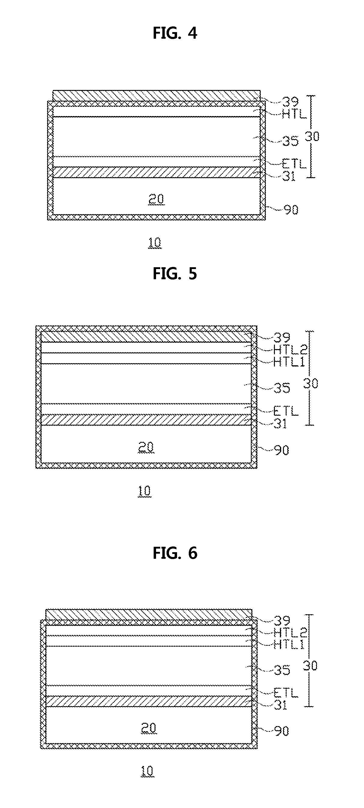
[0094]The direct-conversion-type X-ray detector according to a second embodiment of the present invention includes a quantum dot material for converting X-rays having specific energy into visible light, in addition to the perovskite material as the photoconductor.

[0095]The perovskite material and the quantum dot material may have different X-ray energy ranges in terms of X-ray absorption efficiency, thus advantageously absorbing X-rays across a wide energy range from substantially low energy to high energy.

[0096]The quantum dot material is able to absorb X-rays in the corresponding energy range to thus emit visible light corresponding thereto. The perovskite material is able to absorb X-rays in the corresponding energy range to thus directly produce electron-hole pairs and also to absorb visible light emitted from the quantum dot material to thus produce electron-hole pairs therefor.

[0097]In this way, the X-ray detector of the present embodiment is responsible for a photoelectric co...


PUM

PropertyMeasurementUnit
thicknessaaaaaaaaaa
thicknessaaaaaaaaaa
thicknessaaaaaaaaaa

Abstract

Disclosed is a direct-conversion-type X-ray detector, including a first electrode on a substrate, a semiconductor structure including a photoconductor using a perovskite material on the first electrode, and a second electrode on the semiconductor structure.

Description

TECHNICAL FIELD[0001]The present invention relates to an X-ray detector, and more particularly to an X-ray detector using a perovskite material.BACKGROUND ART[0002]Digital X-ray detectors are classified into indirect-conversion-type X-ray detectors and direct-conversion-type X-ray detectors.[0003]In indirect-conversion-type X-ray detectors, X-rays are converted into visible light using a scintillator, the visible light is converted into an electrical signal using a photodiode, and the electrical signal is detected. Meanwhile, in direct-conversion-type X-ray detectors, a photoconductor for directly generating an electrical signal through absorption of X-rays is used.[0004]In this way, a direct-conversion-type detector is able to detect an electrical signal directly converted from X-rays, thus exhibiting high resolution, conversion efficiency and collection efficiency to thereby reduce radiation poisoning, but is currently problematic because of difficulty in commercialization.[0005]I...

Claims


Application Information

Patent Timeline
Patent Type & Authority Applications(United States)
IPC IPC(8): H01L27/30A61B6/03A61B6/14A61B6/00C09K11/66C09K11/88C09J133/14G01T1/20H01L51/42H01L51/44H01G9/20H01L51/00
CPCH01L27/308A61B6/032A61B6/145A61B6/502C09K11/664C09K11/88C09K11/661C09J133/14G01T1/2018H01L51/426H01L51/441H01L51/448H01G9/2018H01L51/0077G01T1/24A61B6/14A61B6/4233Y02E10/542Y02E10/549H10K39/36H10K30/40H10K30/88H10K85/50G01T1/241C09K11/883C09K11/66C09K11/565H10K30/10H10K30/35H10K30/81H10K85/30
Inventor HEO, SUNG KYNSHIN, DONG HUIKIM, TAE WOOYUN, MIN SEOK
Owner RAYENCE
Why Eureka
Try Eureka