
Low energy electron beam radiation system that generates electron beams with precisely controlled and adjustable penetration depth useful for therapeutic applications

a radiation system and electron beam technology, applied in radiation therapy, x-ray/gamma-ray/particle irradiation therapy, radiation therapy, etc., can solve the problems of difficult feedback control measurement of electron beam spectrum and limited penetration depth adjustment by conventional machines, so as to improve stability and precision, the effect of reducing the energy of electron beams and convenient deploymen

Active Publication Date: 2019-02-21
INTRAOP MEDICAL
View PDF2 Cites 8 Cited by
  • Summary
  • Abstract
  • Description
  • Claims
  • Application Information

AI Technical Summary

Benefits of technology

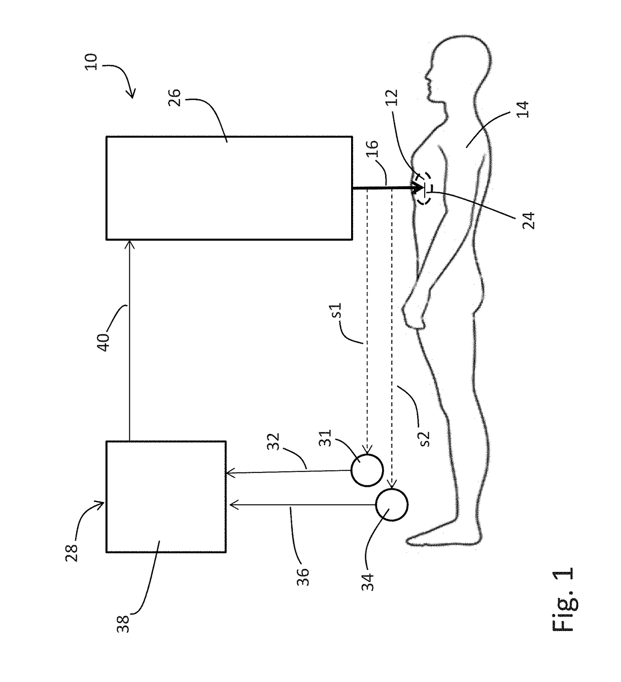
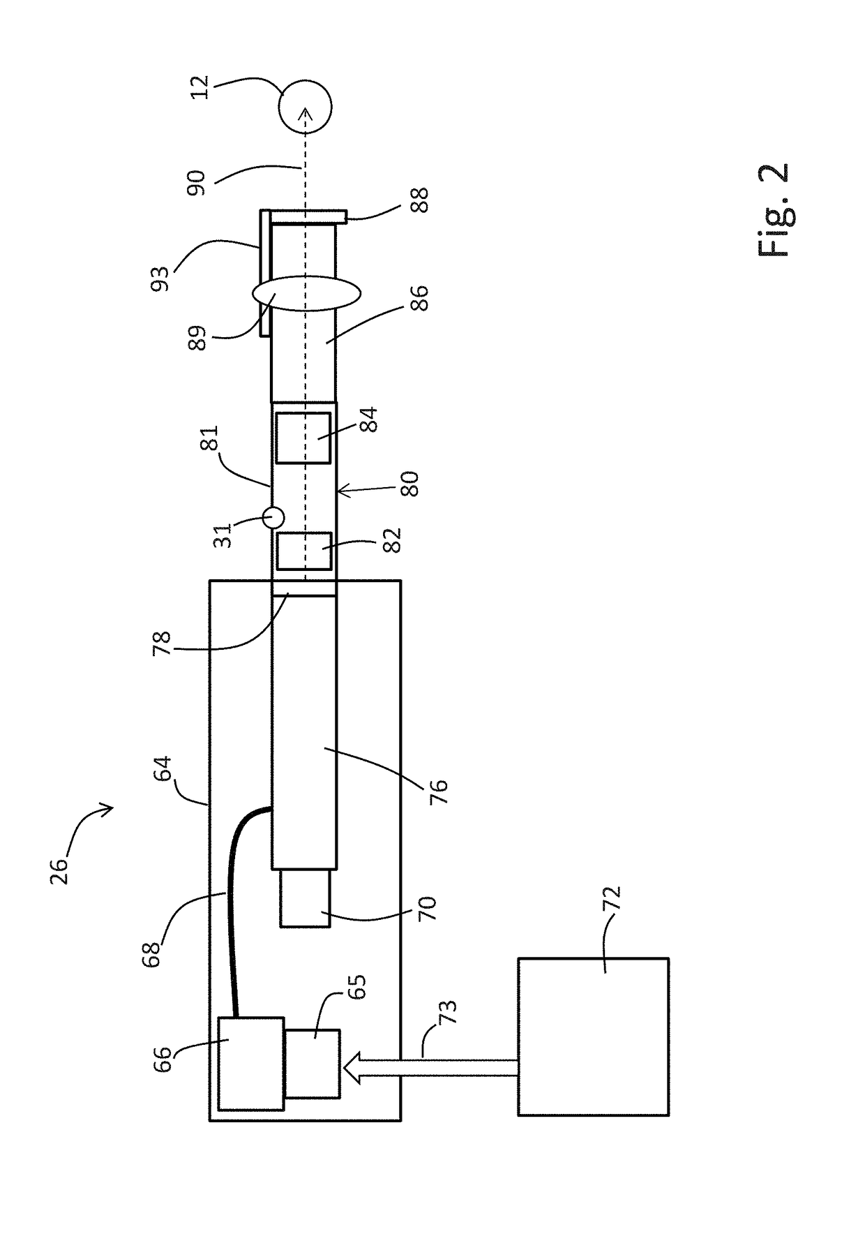
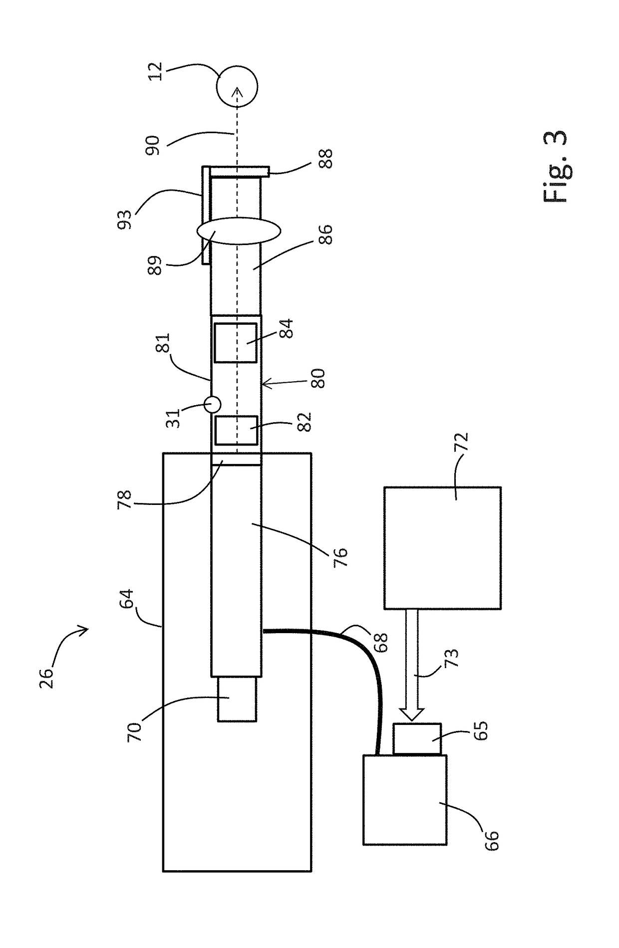
The present invention provides electron beam systems and therapies with improved stability and precision. These machines are compact, lightweight, and can be easily moved around or articulated to provide treatment in intraoperative or other settings. The machines have great flexibility in beam shaping due to the use of applicators or integrated collimator / applicator components described below. The improvement in stability allows for continuous or fine increments of penetration depth settings, even as small as 2 mm or less. The machines can accurately set and adjust electron beam energy at the target site to provide the desired penetration depth. The present invention minimizes dose to healthy or non-involved tissues by confining the radiation treatment field to a narrow or confined area and using lower electron beam energies. The accelerator system is effective in accelerating the electron beam toward the target site.

Problems solved by technology

Measurement of an electron beam spectrum for feedback control has been challenging.
As a consequence, conventional machines have been limited to making much coarser adjustments of penetration depth, such as increments of 1 cm or larger.

Method used


Image

  • Low energy electron beam radiation system that generates electron beams with precisely controlled and adjustable penetration depth useful for therapeutic applications
  • Low energy electron beam radiation system that generates electron beams with precisely controlled and adjustable penetration depth useful for therapeutic applications
  • Low energy electron beam radiation system that generates electron beams with precisely controlled and adjustable penetration depth useful for therapeutic applications

Examples


example 1

[0175]FIG. 12 shows plots of percentage depth dose versus depth in water for various low energy electron beams where the electrons were produced using a Van de Graaff machine (from Gerald J. Hine and Gordon L. Brownell, Radiation Dosimetry, Academic Press, 1956).

[0176]The following Table 1 shows the corresponding R80 penetration depths at different energy levels in water.

TABLE 1R80 depth (millimeters)Electron beam energy (MeV)1.30.52.51.04.82.07.43.0

Note that for electron radiation, the dose just below the surface increases to a maximum value and then falls sharply as the water attenuates the radiation. The data shows that penetration depth in a water phantom correlates strongly to energy level. For example, if the distal R80 penetration depth is plotted against the energy using the data in Table 1, the resultant data is highly linear.

example 2

Effect of Field Flattening Device

[0177]One purpose of scattering foils is to flatten and thereby provide an approximately uniform exposure of radiation to the target site. FIG. 13 illustrates the dose distribution measured perpendicularly to the beam axis. The peaked curve shows field strength prior to flattening. The other curve shows the flattened profile of the electron beam, which provides a more uniform dose distribution over a greater range of off axis positions.

example 3

[0178]FIG. 14 shows percent depth dose as a function of penetration distance in water for 2.1 MeV electron beam system equipped with a 4.5 cm diameter applicator at a 5 cm distance (i.e. gap) from the target surface. Curves are shown for the open 4.5 cm applicator, a 4.5 cm applicator with a 3 cm slit, and a 4.5 cm applicator with a 1.7 cm slit. The slit material is fabricated from DRAIN polymer. For each curve, the surface dose (Io) and the depth of the 90%, 80% and 50% doses are indicated. Note that a slit width less than 3 cm will elevate the surface dose. This data shows that there is a trade-off between slit width and surface dose. If it is desirable to reduce the surface dose, the slit width may need to be larger than the minimum width needed to cover the target.


PUM


Abstract

The present invention provides electron beam therapies with improved feedback control that delivers controlled and adjustable doses of electron beam radiation to variable shallow depths with little radiation exposure to both nearby tissues and tissues below the target. In order to control radiation to accurately penetrate to shallow depths and to allow the radiation to be adjusted to other depth settings in very small or even continuous increments, the present invention senses a plurality of different electron beam characteristics and then uses these to derive a composite characteristic, or analog, of the electron beam energy. The composite analog provides a strong correlation to energy that allows this precision. In another aspect, the present invention relates to implementing this feedback control by adjusting power levels used to establish the electron beam. In other embodiments, feedback control adjusts absorbing components with variable electron beam absorption depending on how such components are presented to the electron beam.

Description

PRIORITY CLAIM[0001]This application claims priority under 35 USC 119 to U.S. Provisional Patent Application No. 62 / 302,077, filed Mar. 1, 2016, the entirety of which is incorporated herein by reference for all purposes.FIELD OF THE INVENTION[0002]The present invention relates to the field of linear, straight through electron beam machines and methods used for therapeutic uses. More particularly, the present invention relates to linear, straight through electron beam machines that incorporate a feedback strategy that allows the electron beam to be generated with controlled and adjustable penetration depth for therapeutic radiation applications.BACKGROUND OF THE INVENTION[0003]Therapeutic radiation often is designed to penetrate deeply into a patient, as most targets for therapeutic radiation are located well below the surface. Even therapeutic radiation used to treat lesions on the skin surface still can penetrate several centimeters below the surface. To allow unaffected (normal) t...

Claims


Application Information

Patent Timeline
IPC IPC(8): A61N5/10
CPCA61N5/1049A61N2005/1059A61N5/1067A61N2005/1074A61N2005/1089A61N2005/1095
Inventor GOER, DONALD A.KRETCHETOV, ALEXANDRE S.WHITTUM, DAVID H.NELSON, JAMES A.
Owner INTRAOP MEDICAL
Learn More