Portable system and method for processing waste to be placed in landfill

a landfill and portable technology, applied in grain treatment, transportation and packaging, nuclear engineering, etc., can solve the problems of large waste solidification area, time-consuming and inefficient process, and large fixed system to achieve sufficient waste solidification in the past, so as to reduce fugitive dust and avoid any substantial delay. , the effect of reducing the amount of dus

Active Publication Date: 2016-04-28
PERRY RIDGE LANDFILL INC
View PDF0 Cites 8 Cited by
  • Summary
  • Abstract
  • Description
  • Claims
  • Application Information

AI Technical Summary

Benefits of technology

[0011]The present invention may utilize one or more solid material feed conveyors, a communicating portable pugmill type liquid / solid mixing unit, and a receiving conveyor for the solidified mixture discharged from the pugmill. The system of the invention enables the more effective and efficient mixing of waste liquids with dry material in order to produce a solidified product suitable for disposal in an active landfill cell. The system enables the landfill to process a wider range of waste materials, such as certain types of coal combustion waste that have proven difficult to dispose of in a typical landfill active cell. Additionally, pugmill processing greatly reduce fugitive dust that might otherwise be released from the waste as it is disposed in the landfill cell. Such dry coal combustion wastes typically consist of all forms of fly ash, bottom ash and other pollution control coal combustion by-products that are amenable to solidifying water-based liquids.
[0012]In a preferred embodiment of the invention, a portable system for processing waste so that it can be made landfill-ready is provided. The waste initially contains free liquids and requires the addition of solids in a solidification process. The system includes a portable pugmill which can be moved to various locations atop an active cell of a landfill; and one or more portable devices for facilitating periodic feeding of the pugmill with waste to be solidified into a landfill-ready state. The waste may be discharged from a truck to the one or more devices, and then may be fed to the pugmill without using long-term storage devices, and avoiding any substantial delay between waste unloading from the trucks and feeding of the pugmill.

Problems solved by technology

This is a time-consuming and inefficient process which requires a large portion of the landfill that could otherwise be devoted to stored waste.
Another processing technique to achieve sufficient waste solidification that has been used in the past has been a large, expensive fixed system, using a processing plant with a fixed pugmill fed by a fixed, large overhead silo not adapted to be portable.
Also, the area of a landfill typically comprises low-grade, unstable materials such as wet clay with little bearing strength, and spongy municipal solid waste (residential garbage).
These issues, including issues of alignment, vibration control, leveling, stability in wind, deterioration in rain and snow, adequate 3-phase electrical power source, and practicality of maintenance, which can routinely be handled by a fixed (non-portable) system, provide many reasons not to attempt to make such a processing system portable.
However, landfill conditions make such an approach problematic.
Such conditions may make it difficult if not impossible to wheel conveyors or other equipment, and outriggers may be needed to stabilize the equipment.
Large capacity solid storage systems are also easily provided with a fixed system (e.g., using a silo), which is problematic if the system is to be made portable.
Such large capacity, tall silos, for example, cannot easily be secured against wind loads, and are difficult to move.
For example, if a system were to be made portable, it must be typically capable of processing 1-2 truckloads (25 tons / load) very rapidly (about 15 minutes / load, while the truck waits) without using tall vertical silos as used in fixed systems, as such silos cannot be safely transported in landfill conditions.
If any portion of the material passes through and drops from the filter in this time, the material is deemed to contain free liquids and cannot be disposed of in a landfill.
Another feature that can render material unsuitable for a landfill is dust.

Method used


Image

  • Portable system and method for processing waste to be placed in landfill
  • Portable system and method for processing waste to be placed in landfill
  • Portable system and method for processing waste to be placed in landfill

Examples


Embodiment Construction

[0036]Set forth below is a description of what are believed to be the preferred embodiments and / or best examples of the invention claimed. Future and present alternatives and modifications to this preferred embodiment are contemplated. Any alternatives or modifications which make insubstantial changes in function, in purpose, in structure, or in result are intended to be covered by the claims of this patent.

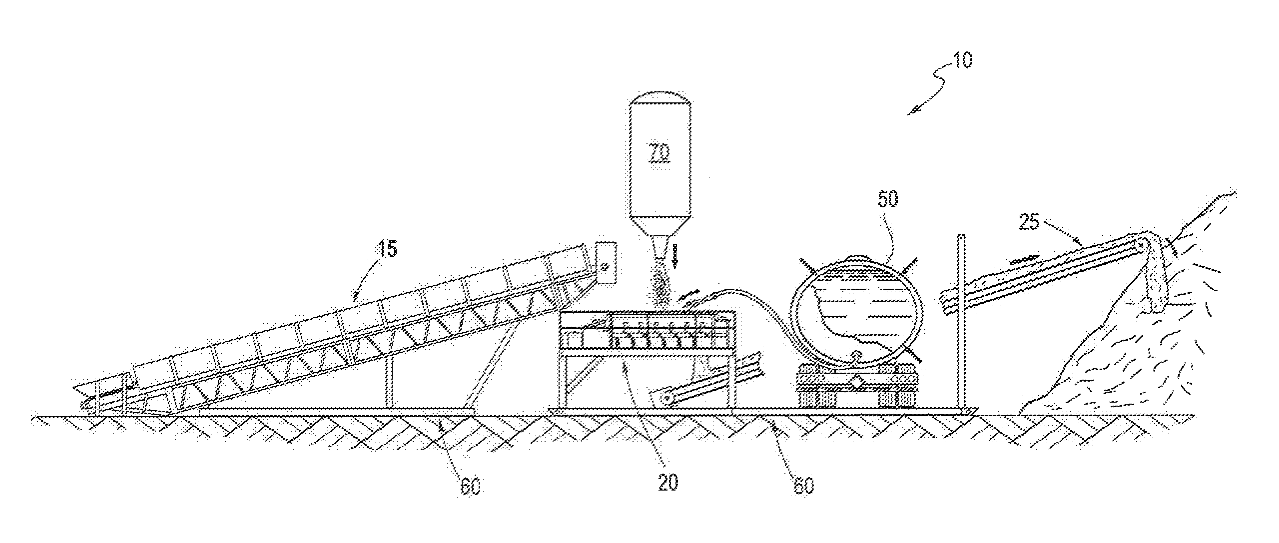
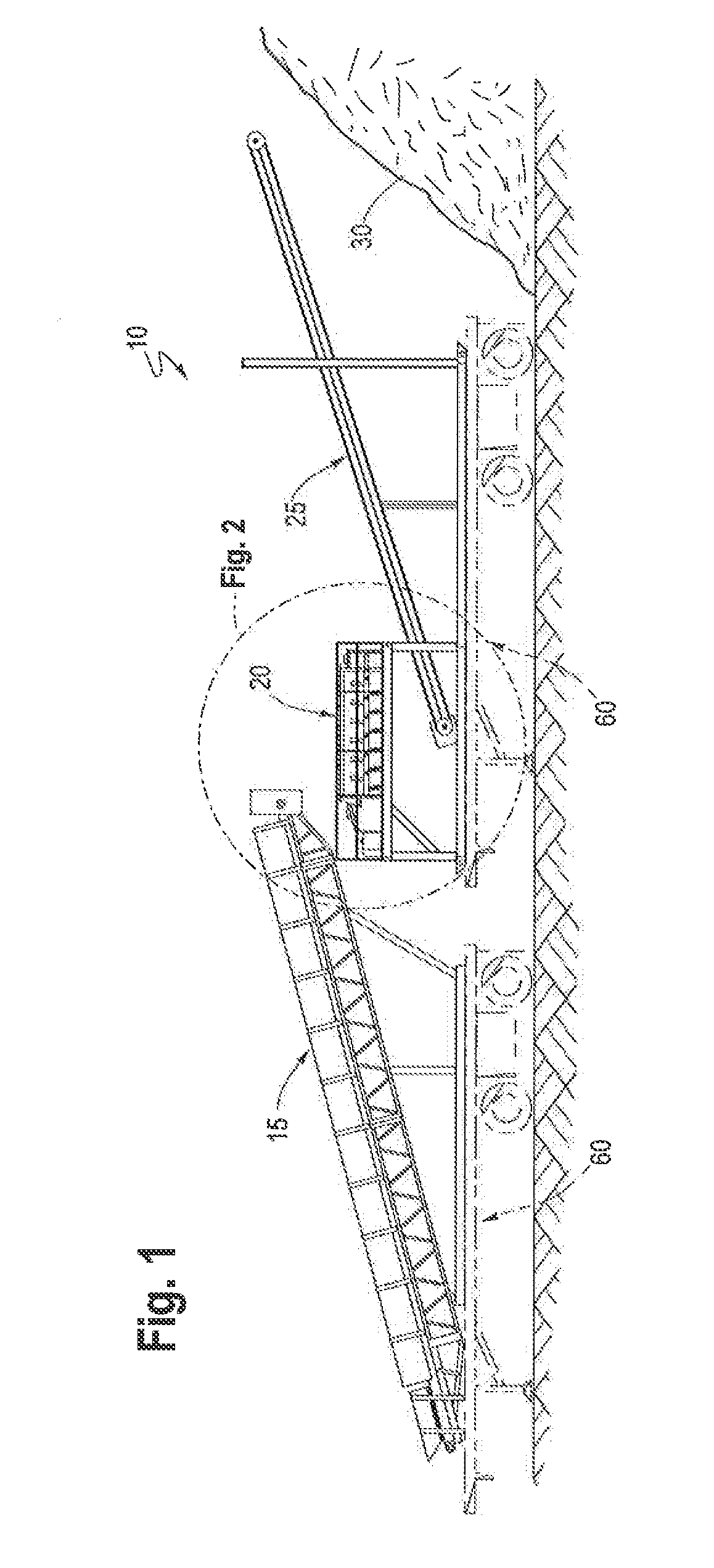
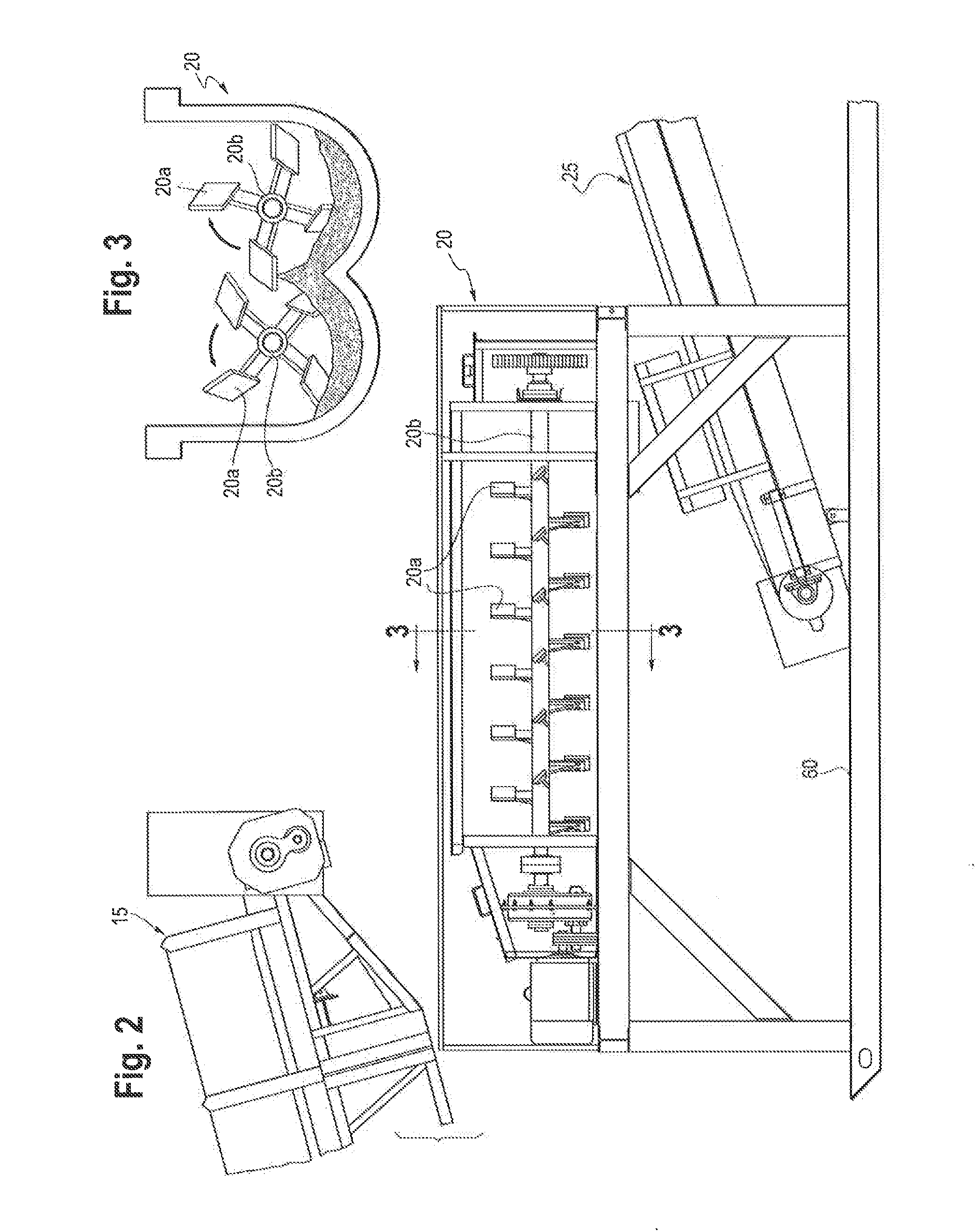
[0037]Referring now to FIG. 1, a preferred embodiment of the portable system of the present invention for solidifying sludge waste and transporting it either to haul trucks for depositing to an active cell of a landfill, or for direct discharge into the active cell, is shown and generally referred to by reference numeral 10. With system 10, dry solids may be truck-fed onto an intake conveyor 15, and discharged into pugmill 20, such as a double-paddle mixing pugmill having blades 20a set on multiple rotor shafts 20b. Simultaneously, a liquid pump (not shown), such as a 3-inch or 4...


PUM

PropertyMeasurementUnit
diameteraaaaaaaaaa
poweraaaaaaaaaa
frequencyaaaaaaaaaa

Abstract

A portable system and method for processing waste to be solidified and placed in an active cell of a landfill. A portable pugmill is moveable adjacent an active cell of a landfill; and portable devices, which may be mounted on sleds or trailers, may be used for feeding the pugmill with waste to be solidified into a landfill-ready state. The waste may be fed to the pugmill without the need for long-term waste storage devices, and avoiding substantial delays between discharge of the waste from trucks to the pugmill-feeding steps.

Description

BACKGROUND OF THE INVENTION[0001]The present invention relates to systems and methods for treating landfill waste using a portable pugmill system.[0002]Operating landfills are provided with liquid and solid waste on a constant basis. Some of these waste materials must be further processed before they can be legally entombed within a landfill. This processing may include mixing waste liquids, sludges and other semi-solid wastes with absorbent materials or other solid (dry) wastes (termed here “waste solidification operations”), before the resulting mixture is sufficiently devoid of any “free liquids” so that it may be legally disposed within an active landfill cell. Examples of liquid wastes that may be treated by the present invention include, but are not limited to, various approved liquid wastes, landfill leachate, or surface water from the landfill or off-site locations.[0003]Currently, the required waste solidification operations may be performed in “batch” processing techniques...

Claims


Application Information

Patent Timeline
Patent Type & Authority Applications(United States)
IPC IPC(8): B09B3/00B09B1/00B09B5/00
CPCB09B3/0008B09B1/00B09B5/00E02D31/00B09B3/20B02C21/02B02C2013/28636B02C23/40B02C23/02B02C2013/28618B09B3/10B09B2101/30B01F23/53B01F27/702B01F33/502
Inventor COUGHLIN, KEVIN J
Owner PERRY RIDGE LANDFILL INC
Why Eureka
Try Eureka