System and method for treating boil-off gas in ship

a technology for treating system and vessel, which is applied in the direction of pressure vessel containers, gaseous engine fuels, non-pressured vessels, etc., can solve the problems of large amount of power consumption, complicated control of the entire system, and bog burning in gas combustion units (gcus) or in atmosphere, so as to save initial installation cost and operation cost, and reduce the amount of bog consumed in gcus or the like , the effect of saving energy consumption

Active Publication Date: 2016-04-28
DAEWOO SHIPBUILDING & MARINE ENG CO LTD
View PDF1 Cites 39 Cited by
  • Summary
  • Abstract
  • Description
  • Claims
  • Application Information

AI Technical Summary

Benefits of technology

[0049]According to the BOG treatment system and method of the present invention, a part of BOG compressed after pressurizing BOG discharged from the storage tank can be supplied as fuel to the vessel engine and the other compressed BOG can be newly discharged from the storage tank to return it to the storage tank by liquefying with cold energy of BOG before compression.
[0050]Therefore, according to the BOG treatment system and method of the present invention, BOG generated from the storage tank can be reliquefied without installing a reliquefaction apparatus consuming a large amount of energy and requiring excessive initial installation cost, thereby saving energy consumed in the reliquefaction apparatus.
[0051]According to the BOG treatment system and method of the present invention, all BOG generated during the transportation

Problems solved by technology

The generated natural gas may increase the inside pressure of the storage tank and accelerate the flow of the natural gas due to the rocking of the vessel, causing structural problems.
In addition, since BOG is loss of LNG, the suppression or reliquefaction of BOG is a very important issue in terms of transportation efficiency.
Therefore, when an amount of fuel necessary for an engine is smaller than a generation amount of BOG, t

Method used


Image

  • System and method for treating boil-off gas in ship
  • System and method for treating boil-off gas in ship
  • System and method for treating boil-off gas in ship

Examples


first embodiment

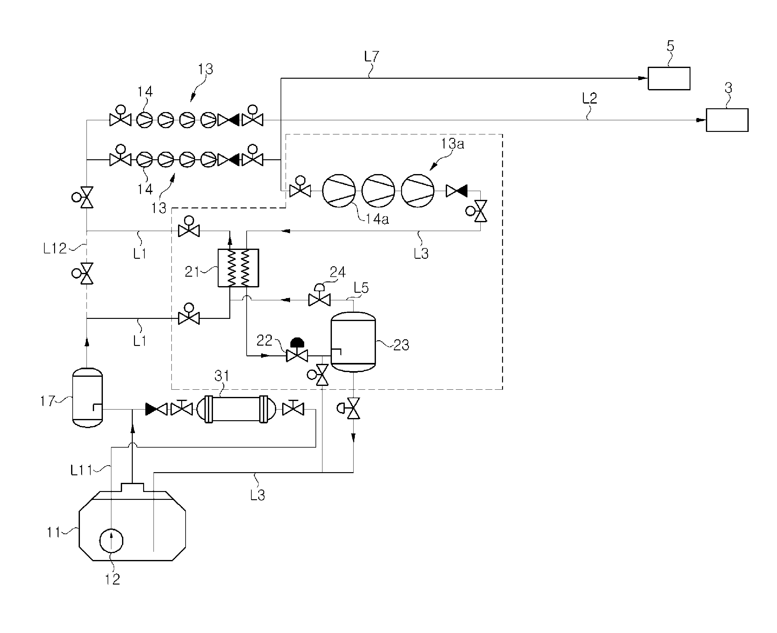
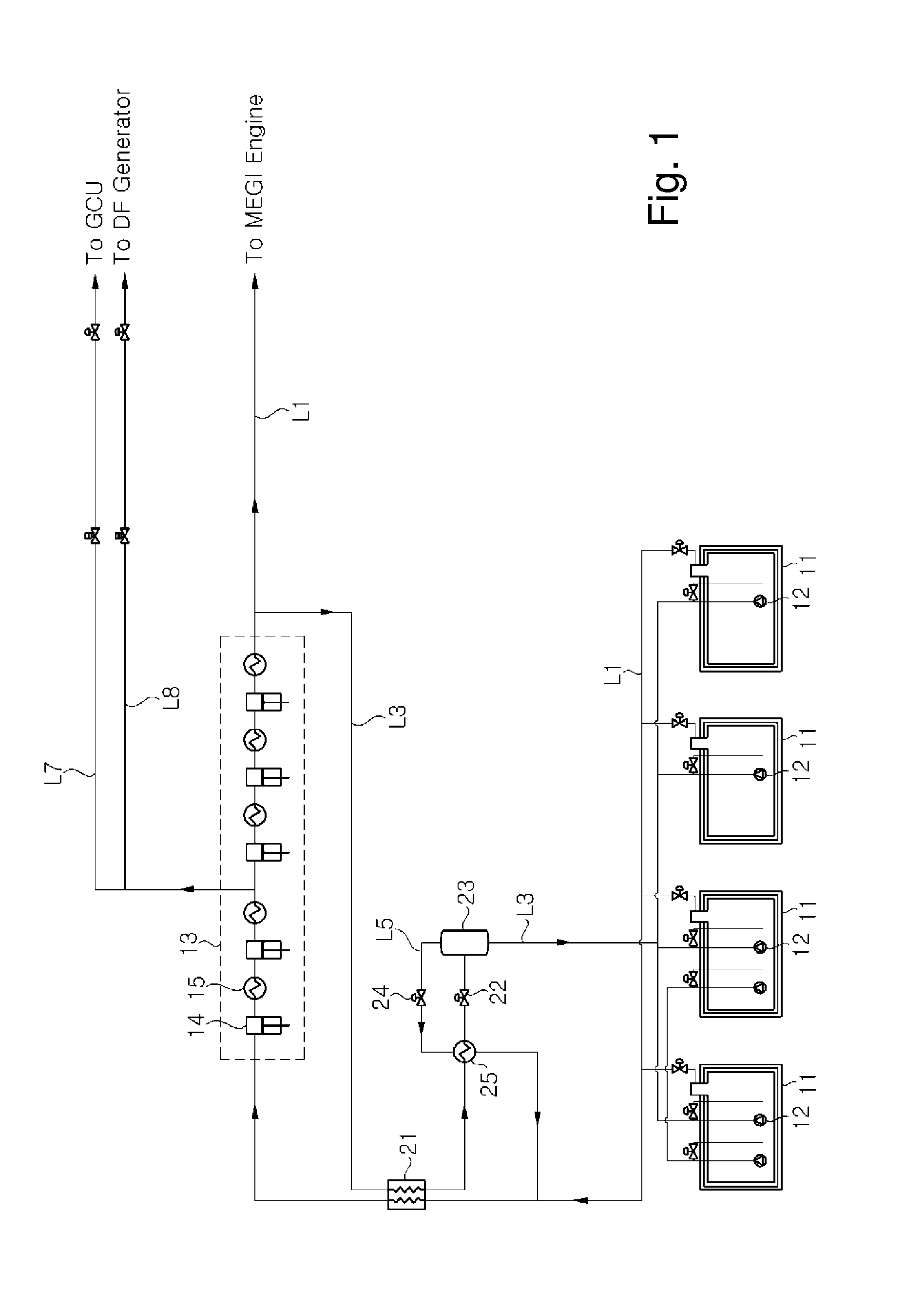
[0073]FIG. 1 is a configuration diagram illustrating a BOG treatment system for a vessel according to the present invention.

[0074]Although FIG. 1 illustrates an example in which the BOG treatment system of the present invention is applied to an LNG carrier equipped with a high pressure natural gas injection engine (e.g., an MEGI engine) as a vessel engine capable of using natural gas as fuel, the BOG treatment system of the present invention can also be applied to any type of vessels (LNG carrier, LNG RV, and the like) and marine plants (FSPP, BMPP, LNG FRU, LNG FPSO, LNG FSRU, and the like), in which a liquefied gas storage tank is installed.

[0075]In the BOG treatment system for the vessel according to the first embodiment of the present invention, boil-off gas (NBOG) generated and discharged from a storage tank 11 storing liquefied gas is transferred along a BOG supply line L1, is compressed in a compressor 13, and is then supplied to the high pressure natural gas injection engine...


PUM


Abstract

In a BOG treatment system, boil-off gas (BOG) discharged from a storage tank is compressed, most of the BOG is used as the fuel of vessel engines, and a remaining part of the BOG is liquefied by cold energy of BOG newly discharged from the storage tank and is returned to the storage tank, thereby efficiently utilizing the BOG. The BOG treatment system for a vessel includes a compressor compressing the BOG discharged from the storage tank; a medium pressure gas engine receiving at least a part of the BOG compressed by the compressor, as fuel; a heat exchanger exchanging heat between the remaining part of the BOG, which is not supplied to the medium pressure gas engine as fuel, and the BOG, which is discharged from the storage tank and is not compressed; and an expander decompressing the remaining part of the BOG cooled by the heat exchanger.

Description

TECHNICAL FIELD[0001]The present invention relates to a boil-off gas (BOG) treatment system and method for a vessel, and more particularly, to a BOG treatment system and method for a vessel, in which BOG discharged from a storage tank is compressed, most of the BOG is used as the fuel of vessel engines, and a remaining part of the BOG is liquefied by cold energy of BOG newly discharged from the storage tank and is returned to the storage tank, thereby efficiently utilizing the BOG.BACKGROUND ART[0002]Recently, the consumption of liquefied gas, such as liquefied natural gas (LNG) or liquefied petroleum gas (LPG), has been rapidly increasing throughout the world. Liquefied gas is transported in a gas state through onshore or offshore gas pipelines, or is transported to a remote consumption place while being stored in a liquefied state inside a liquefied gas carrier. Liquefied gas, such as LNG or LPG, is obtained by cooling natural gas or petroleum gas to a cryogenic temperature (in th...

Claims


Application Information

Patent Timeline
IPC IPC(8): B63H21/38F25J1/00F02C3/22F17C7/04F17C13/00B63B25/16F02M21/06
CPCB63H21/38B63B25/16F25J1/0025F02M21/06F17C2260/03F17C13/004F02C3/22F17C2221/033F17C7/04F02M21/0215F02M21/0221F02M21/023F02M21/0287F17C13/00F17C2201/052F17C2223/0161F17C2223/047F17C2227/0135F17C2227/0178F17C2265/034F17C2265/07F17C2270/0105F25J1/004F25J1/0202F25J1/0277F25J2230/60F25J2245/02Y02T10/30Y02T70/50Y02T90/40B63H21/383F25J2230/08F25J2230/30
Inventor LEE, JOON CHAECHOI, DONG KYUMOON, YOUNG SIKJUNG, SEUNG KYOJUNG, JE HEON
Owner DAEWOO SHIPBUILDING & MARINE ENG CO LTD
Why Eureka
Try Eureka