
Ultrasound System and Method, and Ultrasound Probe

a technology of ultrasound probes and ultrasound systems, applied in ultrasonic/sonic/infrasonic image/data processing, instruments, etc., can solve problems such as artifacts and false images, and achieve the effect of high quality

Active Publication Date: 2016-05-05
HITACHI LTD
View PDF4 Cites 2 Cited by
  • Summary
  • Abstract
  • Description
  • Claims
  • Application Information

AI Technical Summary

Benefits of technology

The present invention is about a method to create high-quality ultrasound images using a technique called pulse inversion. This invention is designed to improve the accuracy and quality of ultrasound examinations.

Problems solved by technology

If the assumption is ineffective, image quality is deteriorated, or in some cases, artifact (false image) is generated.

Method used


Image

  • Ultrasound System and Method, and Ultrasound Probe
  • Ultrasound System and Method, and Ultrasound Probe
  • Ultrasound System and Method, and Ultrasound Probe

Examples


first embodiment

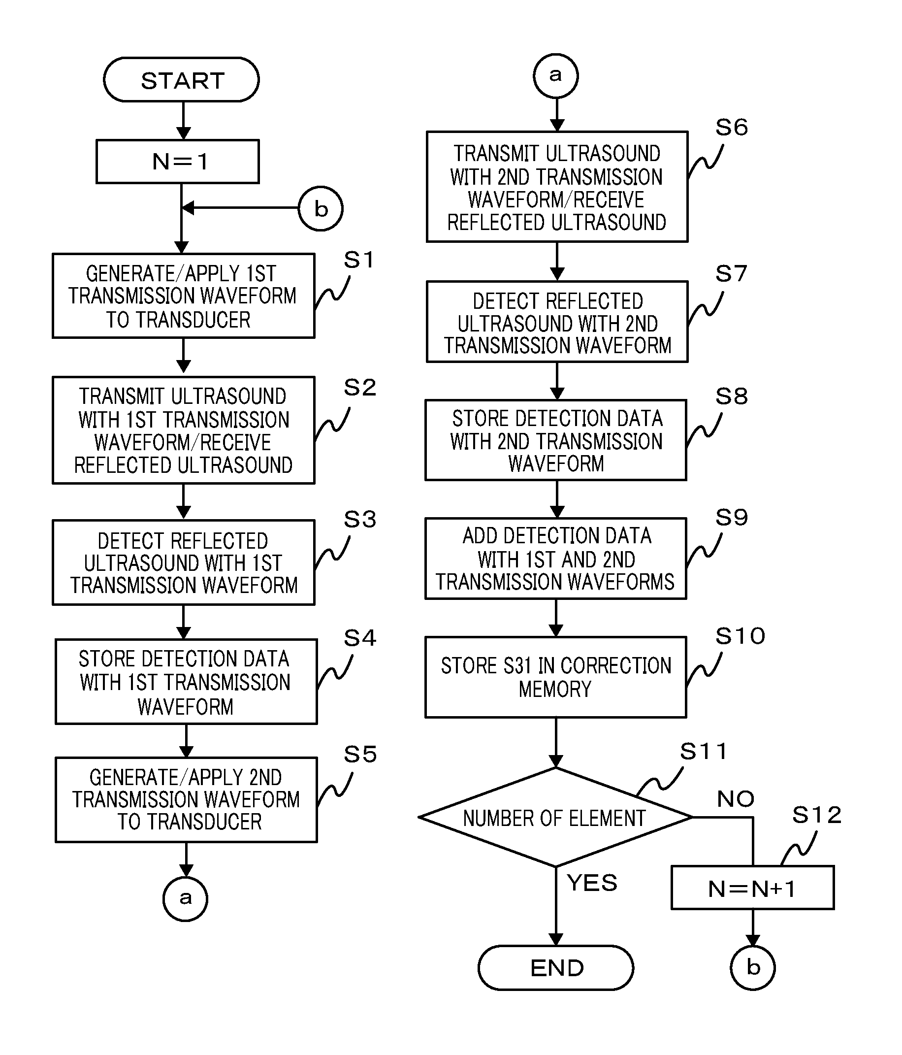
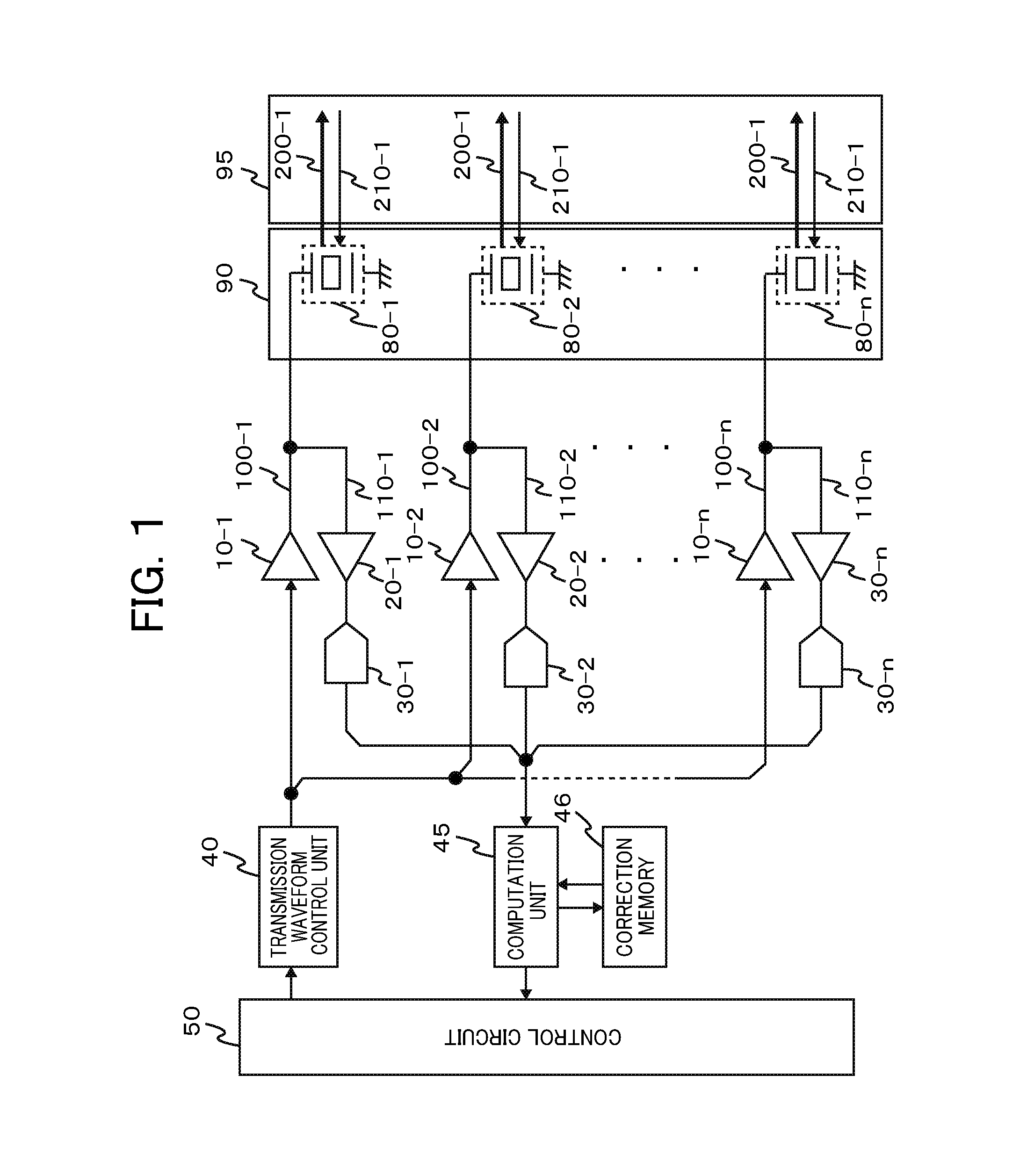
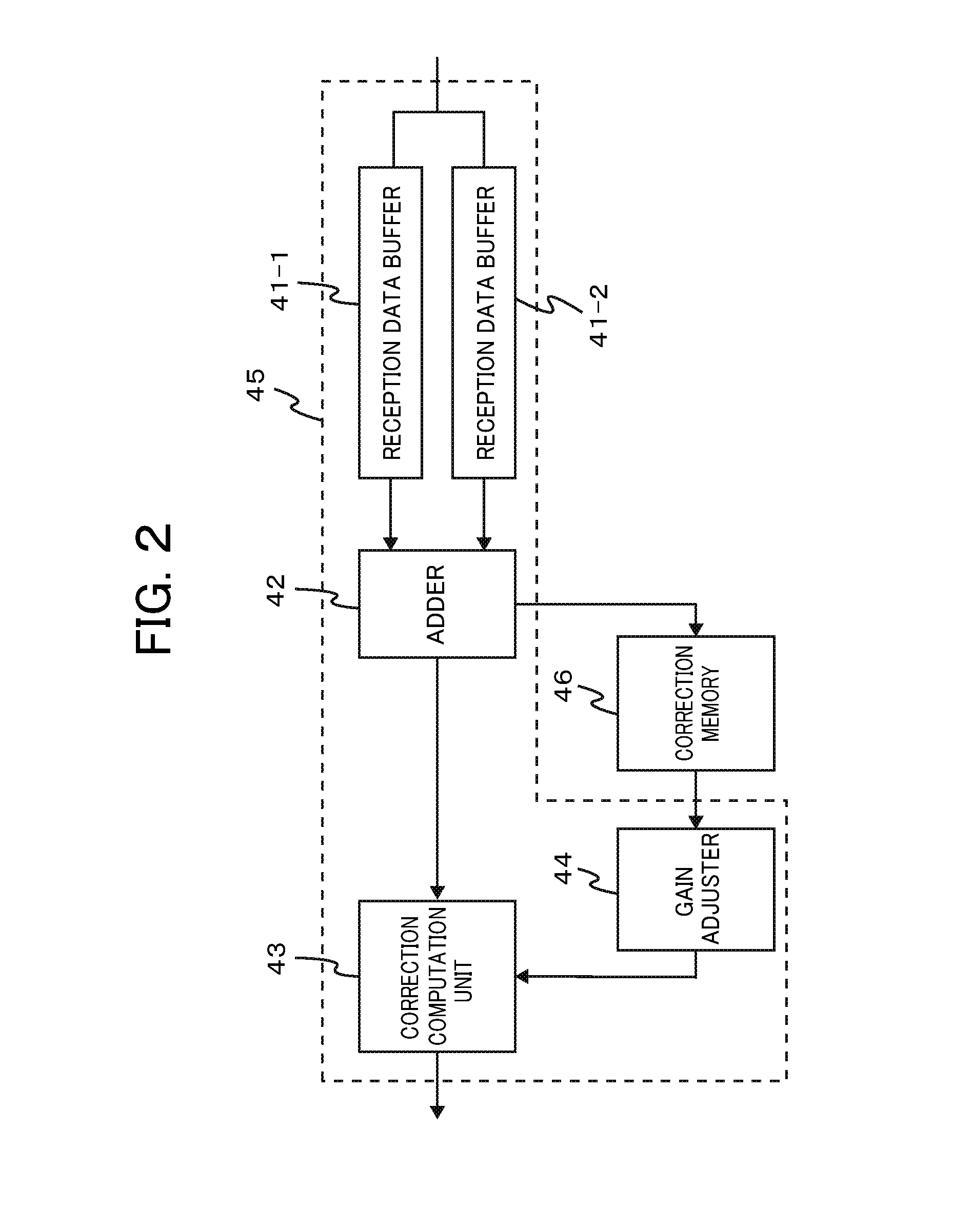
[0024]A first embodiment relates to an ultrasound system which includes a transmission unit which transmits a first transmission signal and a second transmission signal obtained by polarity inversion of the first transmission signal, an ultrasound probe which transmits an ultrasound based on the first transmission signal and the second transmission signal from the transmission unit, and receives an ultrasound as a reflection ultrasound, a reception unit which receives a first reception signal and a second reception signal corresponding to the first transmission signal and the second transmission signal based on the reflection ultrasound received by the ultrasound probe, and a storage unit which stores correction data for correcting a positive-negative asymmetry based on an addition result of the first reception signal and the second reception signal in a calibration mode. The reception unit executes a correction computation using the addition result of the first reception signal and...

second embodiment

[0029]A computation unit in this embodiment is differently structured from the computation unit 45 of the ultrasound system as described in the first embodiment. FIG. 3 shows a structure of the computation unit 45 as a modified example in the reception circuit system which has been described in the first embodiment. Referring to the drawing, only the structure different from the one shown in FIG. 2 will be described. In the calibration mode, the structure is designed to subject the addition data from the adder 42 to Fourier transformation carried out by an FFT processing unit 47. The resultant data are stored in the correction memory 46. In the diagnostic mode, the correction data in the correction memory 46 are read, and inverse Fourier transformed by an inverse FFT processing unit 48. The resultant data are sent to a correction computation unit 43 via an interpolation computation / gain adjuster 49 for correction.

[0030]The embodiment is configured to correct the reception data utili...

third embodiment

[0031]An ultrasound system according to this embodiment is configured to have the correction memory for storing the aforementioned correction data disposed at the side of the ultrasound probe.

[0032]FIG. 4 shows an exemplary structure of the third embodiment. Referring to the drawing, the same components as those described in the first embodiment are designated with the same signs as shown in FIG. 1, and explanations thereof, thus will be omitted. An ultrasound system 300 (main body) and a connector box (BOX) 53 are connected with connectors 51, 52. The ultrasound oscillator array 90 in the overall structure shown in FIG. 1 is disposed at the side of an ultrasound probe 56 in the drawing.

[0033]The correction memory 54 for storing the correction data as described above is disposed in the connector BOX 53. The ultrasound reception signal and the correction data are sent to the computation unit 45 of the ultrasound system (main body) via the connectors 51 and 52 so that the correction c...


PUM


Abstract

An objective of the present invention is to provide an ultrasound system which can correct a positive-negative asymmetry in pulse inversion (PI) and obtain a high-image quality ultrasound image. To carryout an asymmetry correction of a transmission assembly circuit comprising an oscillation adjustment amplifier (10) and an ultrasound oscillator array (90), correction data obtained in a calibration mode is stored in a correction memory (46), and positive-negative asymmetry of an overall receiving assembly circuit comprising a computation unit (45) is corrected in a diagnostic mode of the device using the correction data.

Description

TECHNICAL FIELD[0001]The present invention relates to an ultrasound system, and specifically, the technology aiming at high image quality of the ultrasound system utilizing a pulse inversion method.BACKGROUND ART[0002]The pulse inversion (PI) method has been known as the method for achieving high image quality of the ultrasound image. The PI method is called phase inversion method as the technique for ultrasound imaging with a harmonic content (harmonic) by utilizing nature of the ultrasound resulting from irradiating the living body organ with ultrasound at the single frequency. Specifically, upon ultrasound irradiation, the fundamental wave of the reflection ultrasound reflects at the same frequency with the same polarity as the irradiated ultrasound. On the contrary, the harmonic content of the reflection ultrasound reflects with monopolar regardless of polarity of the irradiated ultrasound. More specifically, a first reflection ultrasound (including the first fundamental wave co...

Claims


Application Information

Patent Timeline
IPC IPC(8): A61B8/00A61B8/14A61B8/08
CPCA61B8/56A61B8/465A61B8/145A61B8/4494A61B8/5207A61B8/08A61B8/4488G01S7/52038G01S15/8963G01S7/52033G01S15/8925G01S15/8927A61B8/58
Inventor IMAGAWA, KENGOIGARASHI, YUTAKAYAZAKI, TORU
Owner HITACHI LTD
Learn More