Improvements relating to power adaptors

a technology of power adaptors and adapters, applied in the direction of ac-dc conversion, efficient power electronics conversion, electrical apparatus, etc., can solve the problems of led light source flicker, triac dimmer misfire, dimmer compatibility, etc., and achieve the effect of minimising the

Active Publication Date: 2016-05-05
ADP CORP LTD
View PDF11 Cites 15 Cited by
  • Summary
  • Abstract
  • Description
  • Claims
  • Application Information

AI Technical Summary

Benefits of technology

[0013]Embodiments of the present invention are advantageous principally because the switch controller providing the high-side switch and the low-side switch with on-times of different durations, on-times that overlap, and / or on-times that are synchronous, may be utilized to control the current delivered to the output without any need to change the frequency at which the resonant circuit is driven. This enables the current at the output to be controlled without changing the frequency at which the resonant circuit is driven, and therefore without any change to the resonant circuit itself.
[0080]When a current spike or current inrush is present, the current may be limited by the resistive load plus the constant current from the constant current circuit. When no current spike or current inrush is present, the constant current circuit feeds the power adaptor. This aspect of the invention is particularly advantageous for power adaptors that draw a substantially constant current, for example utilize an LCL series-parallel resonant circuit or an LC resonant circuit, as discussed above. The constant current circuit is adapted to feed a resonant circuit of the power adaptor, e.g., the LCL resonant circuit, at a current greater than that needed by the resonant circuit, such that the voltage drop across the constant current circuit is minimised.

Problems solved by technology

A major issue with TRIAC dimmable LED bulbs is dimmer compatibility.
If those two currents are not met, the TRIAC dimmer misfires and the LED light source flickers.
Those operating requirements do not cause problems when incandescent bulbs are used, due to their high power consumption.
However, an LED bulb with much less output power cannot maintain this amount of current over the whole line cycle without additional circuitry.
Another issue is the large current spike generated upon firing of a conventional TRIAC dimmer, which is commonly called current inrush.
Such a current spike is generated as a result of the rapid charging of the capacitors of the power adaptor, and has the disadvantage of causing oscillations in the line current.
As discussed above, a TRIAC dimmer requires a latching current during firing and a holding current after firing, and if these current levels are not met then the dimmer may misfire, resulting in flickering of the solid state light source.
Therefore, such oscillations in line current may result in the required current levels not being met and the dimmer misfiring, or may even result in damage being caused to the TRIAC dimmer.
Where the power adaptor is adapted for use with a mains supply and solid state light sources, these sudden changes in current and / or input resistance may cause ringing or harmonics on the mains, possible flicker on the output, and may result in dimmer incompatibility.
This removes any need for a level shifter circuit, which is a high voltage circuit that is typically expensive and results in power loss, and hence reduced efficiency.
This arrangement also removes the need for any feedback transformers, which are large and expensive.
However, the modified output bridge shorts out this signal for approximately the second half, or longer if different dimming curves are required, resulting in the current being drawn at the input for approximately one-half the time expected.
Furthermore, in the case where one low power lamp is connected to a dimmer, if the dimmer becomes unstable and false triggers, the lamp draws power in the double hold manner as described above.
Furthermore, prior art arrangements comprising a FET across a resistive load have been found to suffer from current ringing when the switch is activated—embodiments of the present invention solve this problem.

Method used


Image

  • Improvements relating to power adaptors
  • Improvements relating to power adaptors
  • Improvements relating to power adaptors

Examples


Embodiment Construction

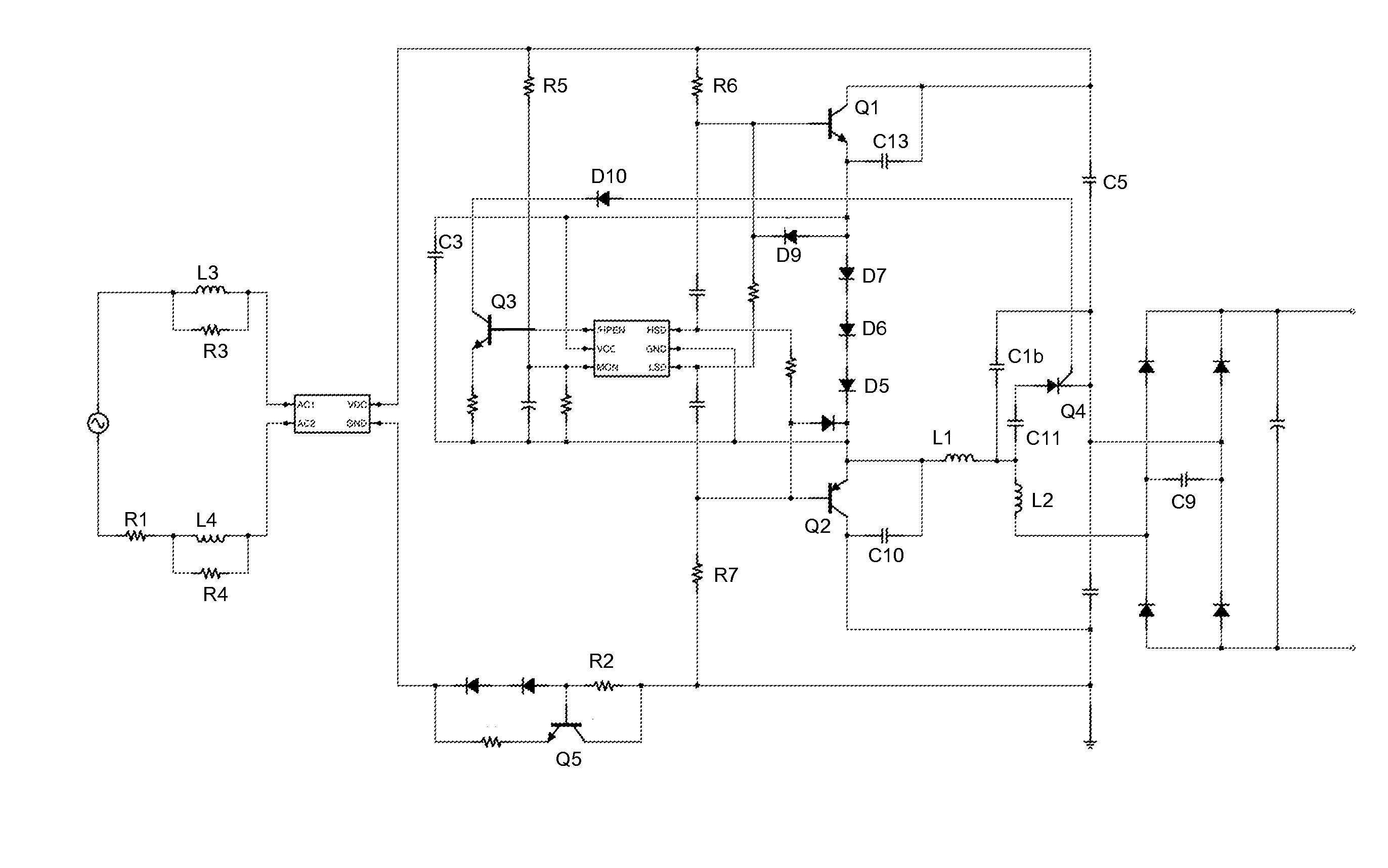
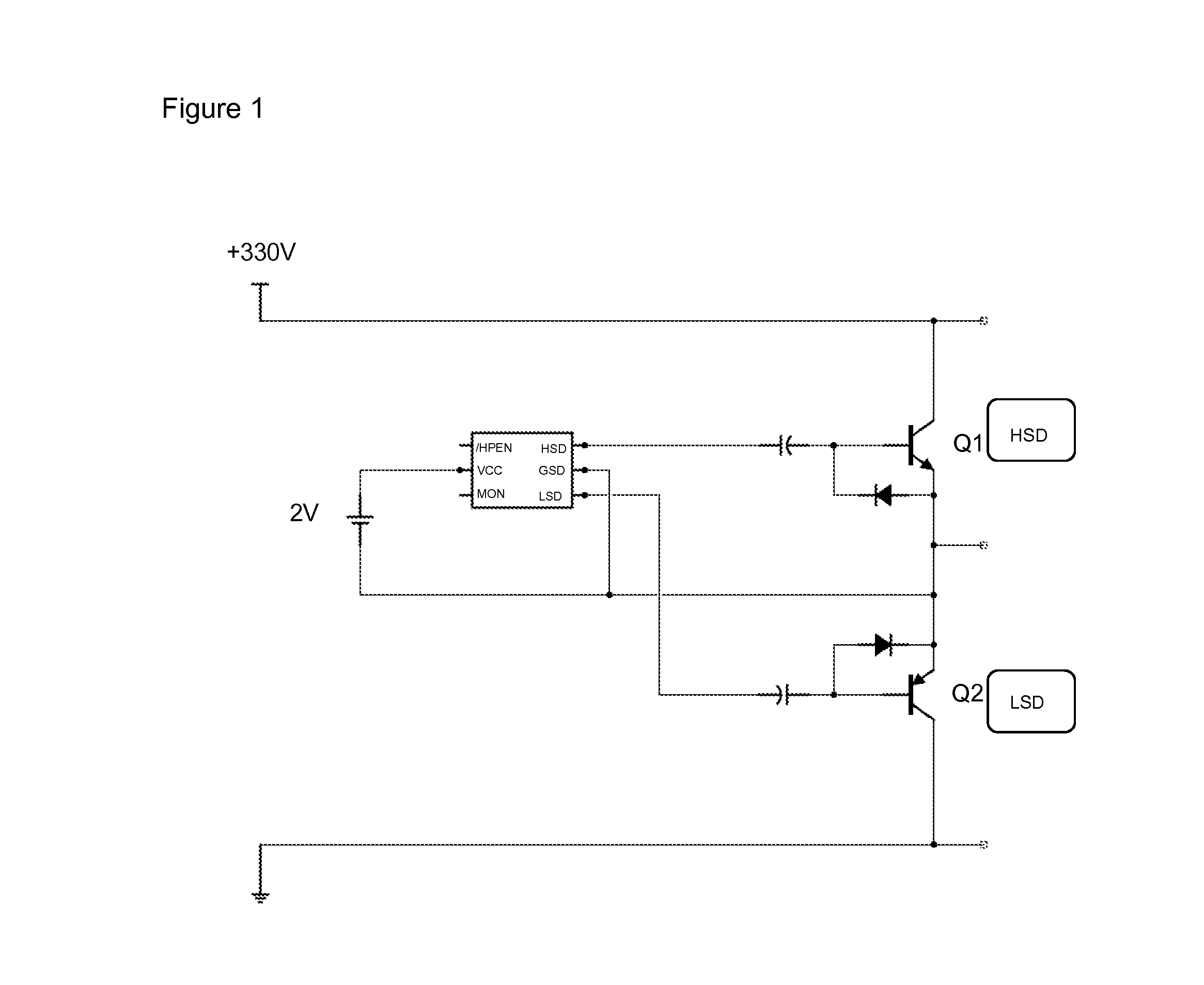
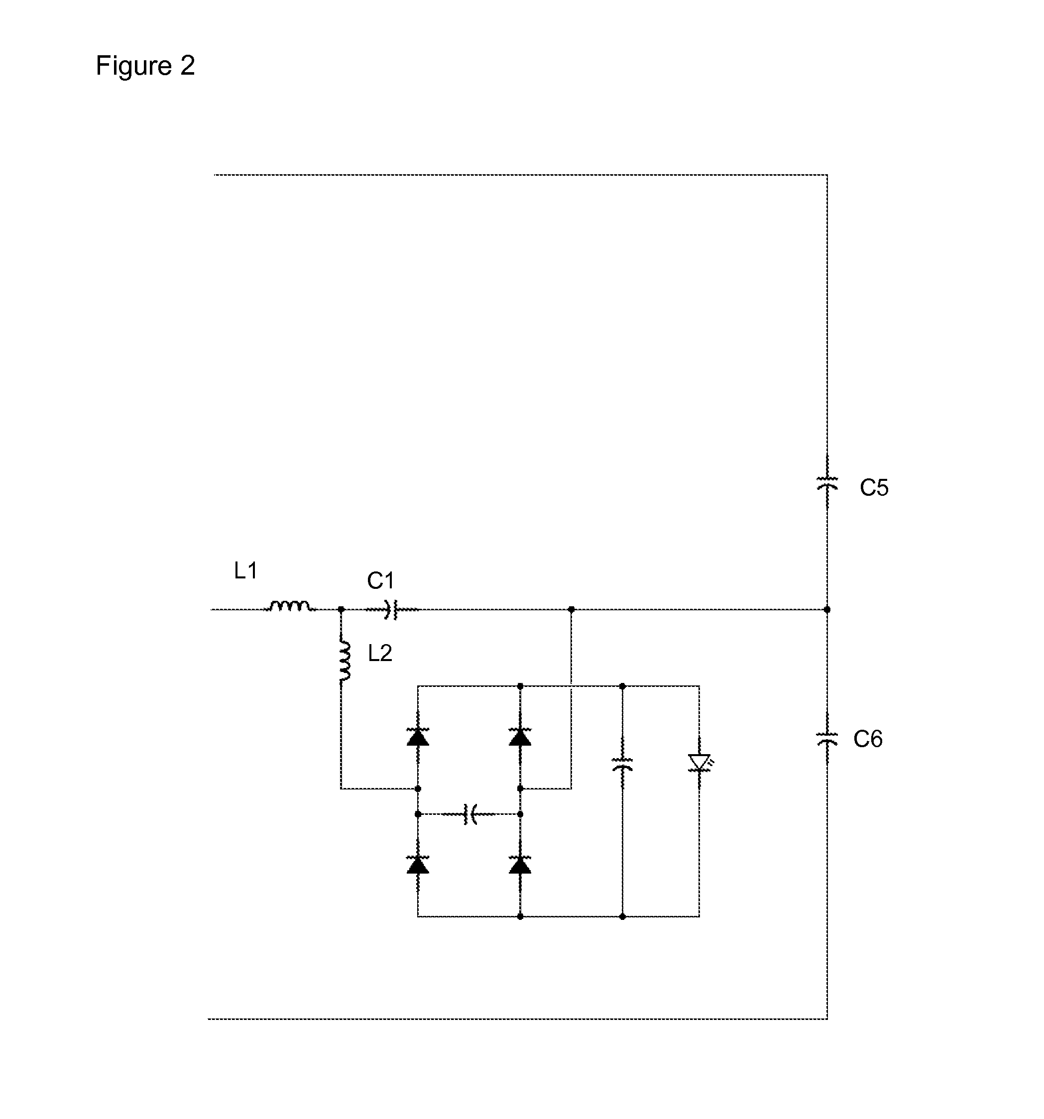
[0095]An embodiment of a power adaptor according to the invention comprises an input rectifier stage (not shown in the Figures), a switch controller (RAIS-DH) and a half bridge drive circuit (HSD,LSD) (shown in FIG. 1), and an LCL series-parallel resonant circuit (L1,C1,L2) and an output rectifier stage (shown in FIG. 2). The high-side switch, Q1, is an NPN BJT transistor, and the low-side switch, Q2, is PNP BJT transistor. Q1 and Q2 are arranged with their emitters / sources connected to a common point, which forms a floating ground for both Q1 and Q2. This common point also provides the output of the half-bridge drive circuit which, in this embodiment, is fed to an LCL series-parallel resonant circuit suitable for driving a solid state light source (of the form described in detail in GB 2449616 B8 and WO 2010 / 041067 A1).

[0096]Q1 and Q2 are each switched by providing a switching pulse to the respective base / gate, the voltage of the switching pulse being referenced to the emitter / sour...


PUM


Abstract

A power adaptor is disclosed, which comprises an input for connection to an AC power supply, a resonant circuit coupled to the input that provides an output suitable for driving a load, at least one half-bridge drive circuit for providing a drive signal to the resonant circuit, and a switch controller for the half-bridge drive circuit. The switch controller is adapted to provide one or more of the following, in at least one mode: (i) to provide the high-side switch and the low-side switch with on-times of different durations, (ii) to provide the high-side switch and the low-side switch with on-times that overlap, and (iii) to provide the high-side switch and the low-side switch with on-times that are synchronous. This may be utilised to control the current delivered to the output without any need to change the frequency at which the resonant circuit is driven.

Description

CROSS-REFERENCE TO RELATED APPLICATIONS[0001]This application claims priority to PCT Application No. PCT / GB2014 / 051602, having a filing date of May 23, 2014, based on GB 1309340.6 having a filing date of May 23, 2013, the entire contents of which are hereby incorporated by reference.FIELD OF TECHNOLOGY[0002]This following relates to power adaptors, and particularly to power adaptors for solid state light sources.BACKGROUND[0003]LEDs are light sources that are being developed to replace conventional lighting systems, such as fluorescent and incandescent lights, in order to provide more energy efficient systems. Since an incandescent light source typically consumes 60-100 W and has a short lifetime, an LED bulb would be the excellent substitute with considerably less power dissipation and longer life. There has therefore been much research into the development of an LED bulb compatible with TRIAC dimmers, which are common in lighting systems.[0004]A major issue with TRIAC dimmable LED...

Claims


Application Information

Patent Timeline
Patent Type & Authority Applications(United States)
IPC IPC(8): H02M7/217H05B33/08H05B37/02H05B44/00
CPCH02M7/217H05B33/0845H05B33/0815H05B37/02H02M1/08H02M7/155H02M7/538H05B45/10H05B45/39Y02B20/30Y02B70/10H02M7/4815
Inventor SUMMERLAND, DAVID
Owner ADP CORP LTD
Why Eureka
Try Eureka