
Apparatus and Method of Determining an Eye Prescription

a technology applied in the field of optical or ophthalmologic methods and apparatuses, can solve the problems of eye problems such as more complex imperfections, progressively more difficult to focus on close objects, and eye irritation, so as to mitigate noise, mitigate noise, and mitigate nois

Active Publication Date: 2016-05-12
MASSACHUSETTS INST OF TECH
View PDF2 Cites 13 Cited by
  • Summary
  • Abstract
  • Description
  • Claims
  • Application Information

AI Technical Summary

Benefits of technology

The patent describes a method for combining multiple sets of data to improve the quality of the data by reducing noise. This can be particularly useful in optical systems that measure the properties of the eye. The method involves registering the data sets and combining them using various techniques to mitigate noise. The resulting data is cleaner and more accurate, and can be used for a variety of applications.

Problems solved by technology

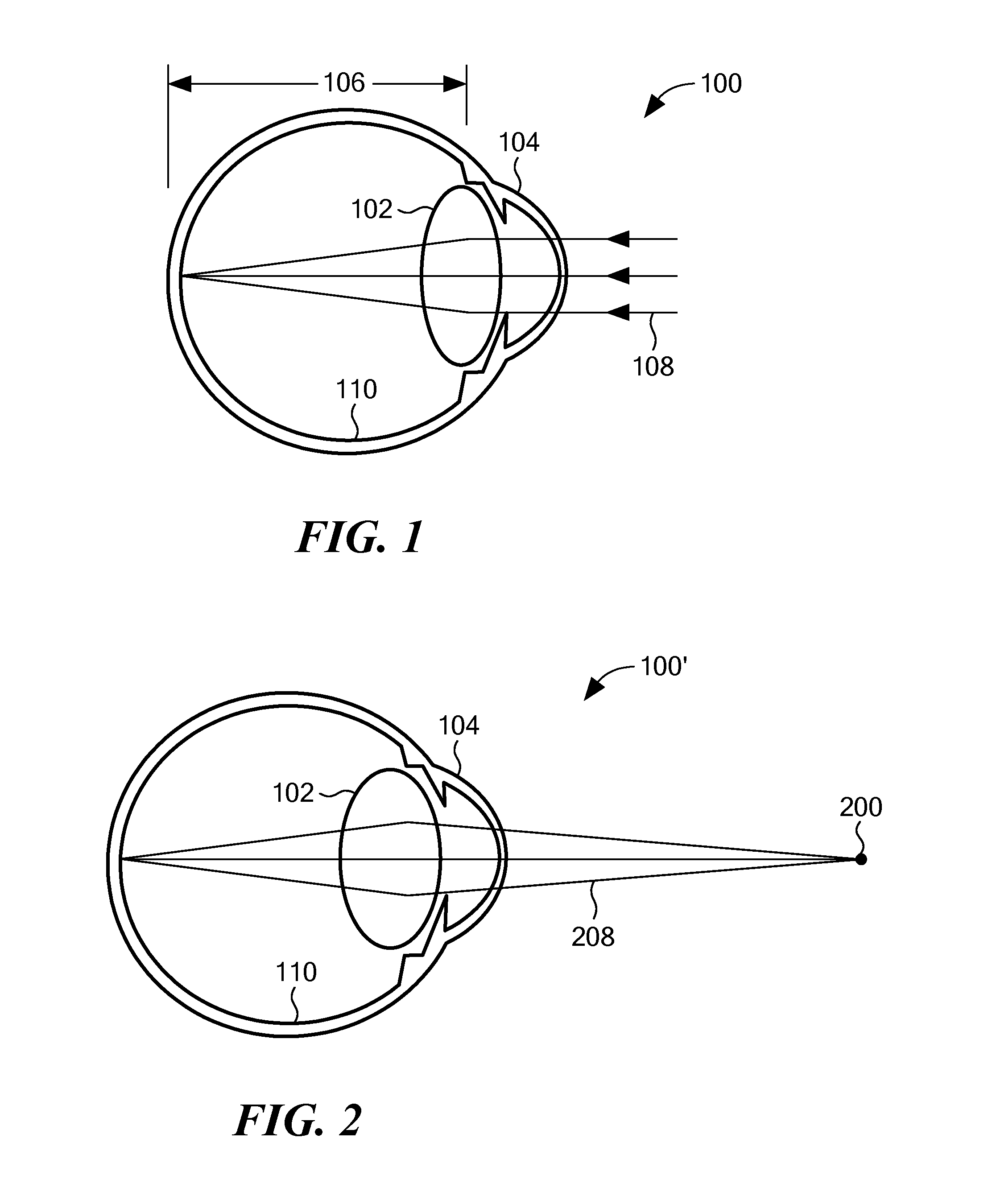
However, focusing on close objects requires effort.
However, with age, the lens 102 becomes increasingly stiff and the ciliary muscles loose some degree of contractility, thereby making it progressively more difficult to focus on close objects.
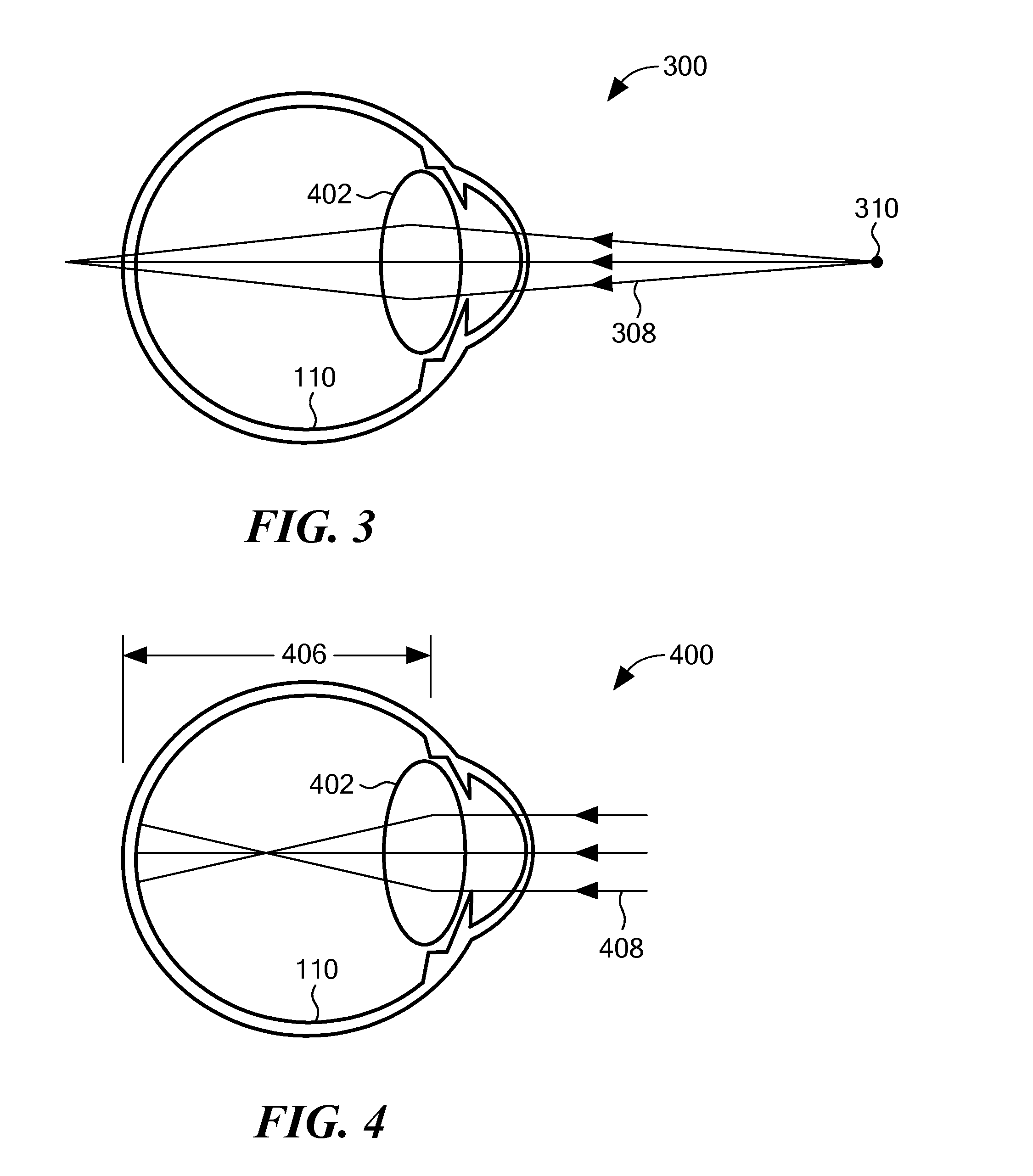
However, eyes may suffer from more complex imperfections, which are commonly referred to as “higher-order aberrations.” Examples of higher-order aberrations include coma and spherical aberration (not to be confused with the low-order spherical imperfections that cause defocus errors, as described above).
Some prescriptions at least partially correct for higher order aberrations, although determining these prescriptions requires large, heavy, expensive, fixed (such as to a desk) diagnostic equipment and highly skilled clinicians.
Phoropters are relatively inexpensive, but the above-described process is time consuming.
All prior art methods and apparatus for determining eyeglass prescriptions have associated problems.
However, if an eye is fogged, and the eye accommodates, vision becomes blurrier, not clearer, regardless of the distance to the object, thus discouraging accommodation.
Some patients do not respond well to fogging.
This phenomenon is sometimes referred to as “instrument-induced myopia,” and it is difficult to avoid, even with fogging techniques.
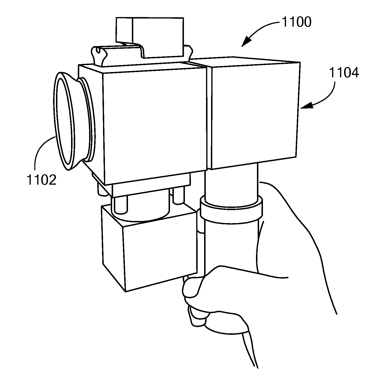
Most ophthalmological diagnostic equipment is large, heavy and mechanically complex, at least in part because the equipment is designed to hold a patient's head steady and align it, and thereby align the patient's eye, with certain optical elements within the diagnostic equipment.
A pinhole does not, however, constrain the angle along which the user can through the pinhole.
A tubular or conic visual channel does, however, constrain the view angle.
Under high ambient light conditions, this noise may reach unacceptably high levels.
However, these approaches have limitations.
For example, the patient may not be positioned with her head vertical, thereby making a vertical orientation of the apparatus an incorrect orientation.
However, if the eye is grossly misaligned with the optical axis, none of the spot diagram falls on the optical sensor, or an insufficient portion of the spot diagram falls on the optical sensor for the spot diagram centroid calculator 2802 to calculate a centroid location.
Nevertheless, a patient may at times accommodate while her eye is being measured.
On the other hand, cylindrical correction does not vary significantly with amount of accommodation, so if variations in the cylindrical components of the prescriptions are found, these are in general indicatives of undesirable movements of the patient during the test.
However, embodiments of the present invention do not necessarily accept the greatest candidate spherical prescription as the correct prescription, because a candidate prescription may be a result of noise and the magnitude and direction of the accommodation may depend on or other factors such as the actual refractive error of the patient.
Thus, candidate prescriptions with no nearby candidate prescriptions are very likely a result of noise.
The errors in determining the centroids of these spots from specular noise can then cause large errors in the calculation of the Zernike coefficients corresponding to the defocus of the eye.
In general, frames with bright spots in their spot diagrams have better signal-to-noise than frames with dim spots, although a large number of spots that are saturated is undesirable.
However, the exposure time should not be increased to a value that might cause motion blur as a result of the eye moving.
Thus, some frame may not contain useful information.
Furthermore, even if the patient's eye does not move, intraocular fluid, such as vitreous humor, may flow, causing optical interference.
It is also to take into account at this stage that only frames which are close in time (i.e. consecutive frames in which the eye had no time to accommodate) may be combined, since accommodation can cause the combination of frames with different prescriptions leading to incorrect results.
Therefore, prescriptions calculated from spot diagrams captured while a patient is accommodating are unlikely to be accurate.
Thus, some prescription values may not have been calculated from any accepted frames.

Method used


Image

  • Apparatus and Method of Determining an Eye Prescription
  • Apparatus and Method of Determining an Eye Prescription
  • Apparatus and Method of Determining an Eye Prescription

Examples


Embodiment Construction

[0006]An embodiment of the present invention provides a method of determining an optical property of an eye of a living being. The method includes providing an optical apparatus that has a proximal port and a distal port. The proximal port and the distal port together form a visual channel. The eye is aligned with the proximal port. Target indicia are produced at effective infinity. The target indicia are viewable through the visual channel. The eye is focused on the target indicia. Accommodation of the eye is determined, as the eye views the target indicia. An optical property for the eye is calculated, as a function of the determined accommodation.

[0007]Data may be gathered relating to accommodation of the eye. Calculating the optical property may include using the data relating to accommodation to identify when the eye is accommodating and when the eye is not accommodating. Calculating the optical property may include selecting data relating to when the eye is not accommodating t...


PUM


Abstract

Eye prescriptions may be determined by providing a simple, easy to use, portable device with a specially configured targeting light source that aligns the eye, mitigates accommodation, and provides accurate results. Unlike stationary, closed view autorefractors, this device typically is portable, self-usable, relatively inexpensive, enabling more widespread use across the world.

Description

CROSS REFERENCE TO RELATED APPLICATIONS[0001]This application claims the benefit of U.S. Provisional Patent Application No. 61 / 842,190, filed Jul. 2, 2013, titled “System and Method for Optical Alignment of an Eye with a Device for Measurement of Optical Properties of the Eye,” U.S. Provisional Patent Application No. 61 / 972,058, filed Mar. 28, 2014, titled “Apparatus and Method for Determining an Eye Prescription” and U.S. Provisional Patent Application No. 61 / 972,191, filed Mar. 28, 2014, titled “Apparatus and Method for Determining an Eye Prescription,” the entire contents of all of which are hereby incorporated by reference herein, for all purposes.TECHNICAL FIELD[0002]The invention generally relates to optical or ophthalmologic methods and apparatus and, more particularly, the invention relates to methods and devices for facilitating the process of determining optical properties of an eye.BACKGROUND ART[0003]“Refractive errors” are low-order aberrations, such as in an eye of a h...

Claims


Application Information

Patent Timeline
Patent Type & Authority Applications(United States)
IPC IPC(8): A61B3/10A61B3/15A61B3/14A61B3/103A61B3/00
CPCA61B3/1015A61B3/103A61B3/0025A61B3/145A61B3/152A61B3/113A61F9/008A61B3/0091A61B3/18A61B3/0041A61B5/7415A61B5/7455A61B2560/0425
Inventor DURR, NICHOLAS J.NEGRO, EDUARDODAVE, SHIVANG R.
Owner MASSACHUSETTS INST OF TECH
Learn More