
Needleless, Intermittent, Neutral Displacement IV Injection Port

a technology of neutral displacement and injection port, which is applied in the direction of valves, infusion devices, other medical devices, etc., can solve the problems of increasing the risk of new patients, affecting the safety of new patients, and accidental needle stick injuries among healthcare providers, etc., and achieves excellent blood flushing characteristics, reduce dead space, and small priming volume

Active Publication Date: 2016-05-12
FRESENIUS KABI DEUT GMBH
View PDF6 Cites 24 Cited by
  • Summary
  • Abstract
  • Description
  • Claims
  • Application Information

AI Technical Summary

Benefits of technology

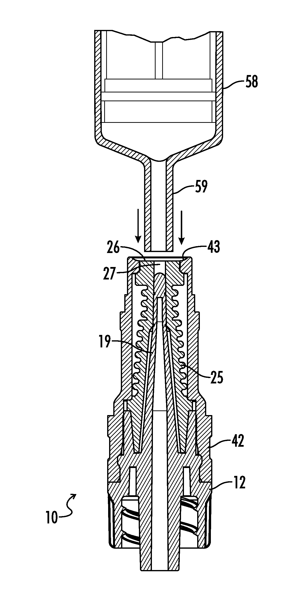
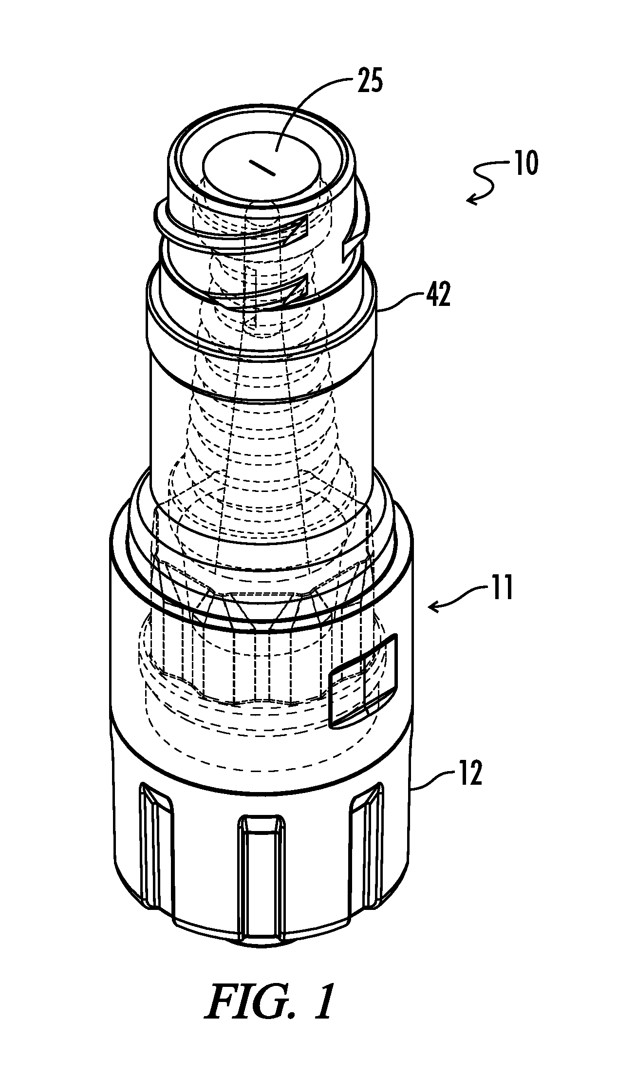
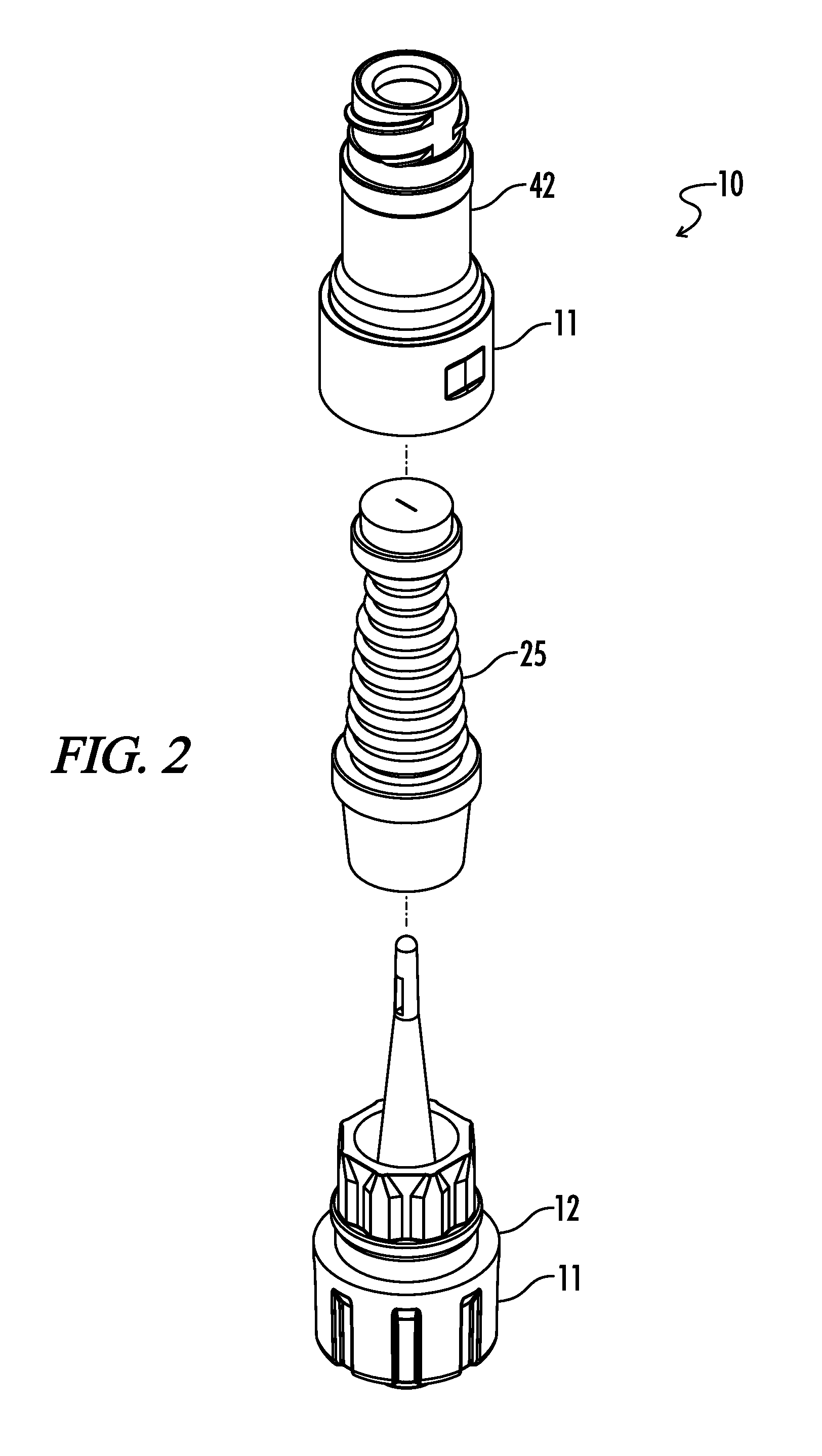
The present invention provides an improved compression-fit septum seal integrity with reduced gaps or openings, and improved septum disinfection capabilities with a 3-piece component assembly. The invention also provides an improved non-torturous fluid pathway with reduced dead space, small priming volume, clinically acceptable fluid flow rates for all medical procedures, and excellent blood flushing characteristics. The invention helps prevent fluid leakage within the injection ports fluid pathway, and improve back-pressure capabilities. Additionally, the invention helps provide an improved manufacturing assembly process to help reduce overall costs and increase productivity for the final assembly of the injection port.

Problems solved by technology

An accidental needle stick injury among healthcare providers was a common occurrence.
Accidental punctures by contaminated needles can inject hazardous fluids into the body through the skin.
Ever since needleless, intermittent injection ports were introduced to the markets in the early 1990's, two major patient safety issues have evolved; a significant increase in catheter-related bloodstream infections (CR-BSIs) and intraluminal thrombotic catheter occlusions (blood clots within the vascular-access catheter).
It appears that needleless injection ports solved one major healthcare issue of eliminating accidental needlestick injuries, but, inadvertently created new patient safety issues.
CR-BSI is not only one of the highest mortality infections in the hospital, but it also significantly increases hospital length of stay, with additional health care cost estimates of over $50,000 per occurrence (over $12 billion annually).
A second patient safety issue that has developed since the introduction of needleless injection ports is intraluminal thrombotic catheter occlusions, or blood clots within the vascular-access catheter.
Any of these events can negatively affect the patient's hospital experience.
Clinical complications associated with catheter occlusions can cost significant time and money and are also a critical factor in the overall patient care equation.
It is surmised that an intraluminal thrombosis may serve as a nidus for infections, perhaps due to the blood fibrin and biofilm depositions, thereby affecting the patient's health and increasing hospital costs.
Poorly designed septum seal integrity, large gaps or openings at the critical outer septum area (or entry point), could allow microbial contamination ingress into the patient's injection port fluid pathway.
Additionally, septum surface designs could make effective disinfection of the septum surface very difficult prior to accessing the needleless injection port; which could lead to downstream contamination into the patient's bloodstream.
Most conventional needleless injection ports have torturous fluid pathways within their valve system designs that exhibit dead spaces that are difficult to effectively flush blood, air bubbles, and / or critical drugs from the injection port.
This leads to large priming volumes (the amount of fluid to fill the fluid pathway of the needleless injection port), which increases the possibility for dead spaces within the injection port fluid pathway.
The problems mentioned above can potentially be harmful to a patient or otherwise undesirably jeopardize the safety of the patient.
This manufacturing process can be difficult and time consuming, as well as costly.

Method used


Image

  • Needleless, Intermittent, Neutral Displacement IV Injection Port
  • Needleless, Intermittent, Neutral Displacement IV Injection Port
  • Needleless, Intermittent, Neutral Displacement IV Injection Port

Examples


Embodiment Construction

[0049]While the making and using of various embodiments of the present invention are discussed in detail below, it should be appreciated that the present invention provides many applicable inventive concepts that is embodied in a wide variety of specific contexts. The specific embodiments discussed herein are merely illustrative of specific ways to make and use the invention and do not delimit the scope of the invention.

[0050]To facilitate the understanding of the embodiments described herein, a number of terms are defined below. The terms defined herein have meanings as commonly understood by a person of ordinary skill in the areas relevant to the present invention. Terms such as “a,”“an,” and “the” are not intended to refer to only a singular entity, but rather include the general class of which a specific example may be used for illustration. The terminology herein is used to describe specific embodiments of the invention, but their usage does not delimit the invention, except as...


PUM


Abstract

An injection port assembly including a body having first and second mating structures configured to mate with a first connector for a first fluid pathway and a second connector on a device, respectively. A resilient barrier substantially contained within the body and compressible from a first position in which fluid flow between the first and second connectors is blocked to a more compressed second position in which fluid flow between the first and second connectors is permitted. A hollow cannula can be coupled with the first mating structure and disposed within the resilient barrier, the hollow cannula having a distal end configured to extend through the resilient barrier when the resilient barrier is in the second position, the distal end having lateral slots. The resilient barrier can have first and second annular sealing rings positioned above and below the lateral slots respectively.

Description

CROSS-REFERENCE TO RELATED APPLICATIONS[0001]This application claims the benefit of priority to U.S. Provisional Application No. 62 / 078,740, filed on Nov. 12, 2014, which is hereby incorporated by reference in its entirety.TECHNICAL FIELD OF THE INVENTION[0002]The present disclosure relates generally to medical intravenous administration line connectors. More particularly, this disclosure pertains to a needleless, intermittent, neutral fluid displacement injection ports for safe infusion of IV fluids, antibiotics, lipids, blood, blood components or drug products and / or blood aspiration in intravenous and blood administration therapy.BACKGROUND OF THE INVENTION[0003]In the mid-1980's, concern grew publically worldwide within the healthcare community for a new and potentially lethal virus called the Human Immunodeficiency Virus (HIV) which leads to AIDS (Acquired Immune Deficiency Syndrome). Prior to the AIDS epidemic, IV therapy and blood collection methods utilized hypodermic syring...

Claims


Application Information

Patent Timeline
Patent Type & Authority Applications(United States)
IPC IPC(8): A61M39/10A61M5/162
CPCA61M39/1011A61M5/162A61M2039/1072A61M2039/262A61M2039/267
Inventor RYAN, DANA WM.
Owner FRESENIUS KABI DEUT GMBH
Learn More