A stabilized platform for a wireless communication link

a wireless communication link and platform technology, applied in the direction of collapsible antennas, directions finders, antennas, etc., can solve the problems of limiting the communication distance to a length of no more than, difficulty in correctly aligning the two ends of a terrestrial link, and difficulty in maintaining mutual alignment of the ends of the link, so as to improve the accuracy

Active Publication Date: 2016-05-12
EM SOLUTIONS PTY LTD
View PDF1 Cites 190 Cited by
  • Summary
  • Abstract
  • Description
  • Claims
  • Application Information

AI Technical Summary

Benefits of technology

[0026]The step of redirecting the first antenna in response to variations in the beacon signal may involv

Problems solved by technology

Although mm-wave communications systems can support gigabit-per-second data throughput, they have a susceptibility to atmospheric attenuation which limits communications distances to lengths of no more than several miles, and only in good weather.
However these systems require use of a lower frequency backup transceiver in the event of adverse weather.
However, as some of these patents describe, the narrow beamwidth at mm-wave frequencies also creates difficulty in correctly aligning two ends of a terrestrial link that are separated by large distances, since the antennas need to point directly at each other to avoid missing each other's narrowly focused beams.
As previously alluded to, a problem that arises with a system such as that of FIGS. 1 and 2, which is particularly pronounced where the link operates at millimeter wavelength frequencies, is that it is difficult to maintain mutual alignment of the ends of the link.
This problem arises because the operati

Method used


Image

  • A stabilized platform for a wireless communication link
  • A stabilized platform for a wireless communication link
  • A stabilized platform for a wireless communication link

Examples


Embodiment Construction

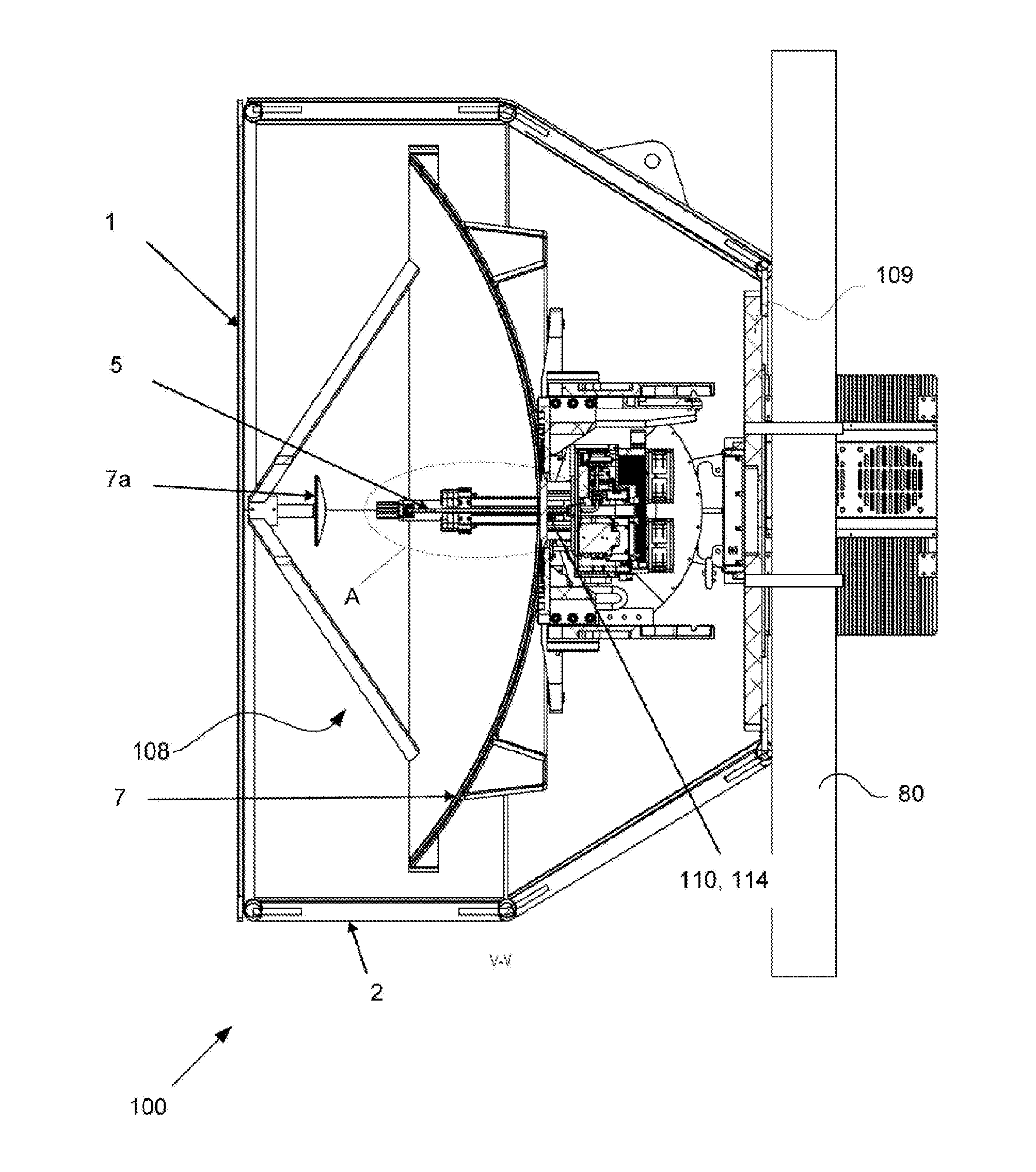
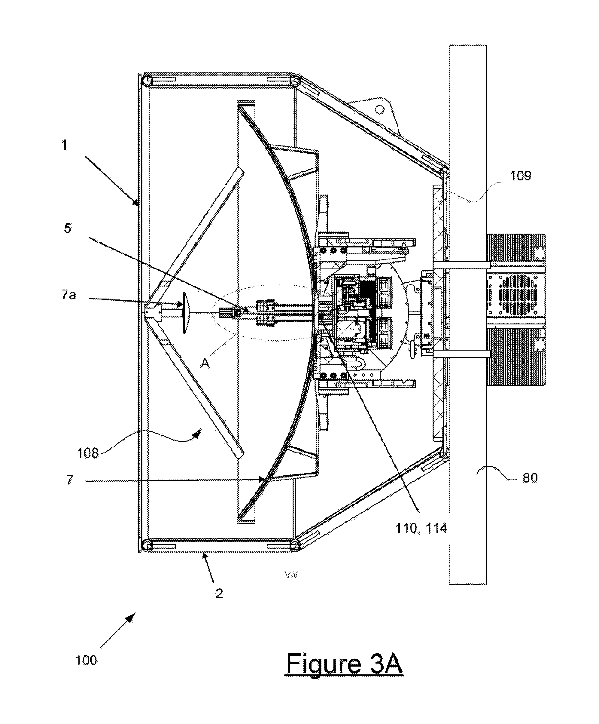
[0104]Referring now to FIGS. 3A to 3E, there is depicted an antenna assembly or “link end”100 according to a preferred embodiment of the present invention. As will be explained, the link end 100 includes a redirecting assembly in the form of a two axis gimbal 3 that has x and y pivots 104, 106. One side of the gimbal 3 comprises a gimbal platform 109 that is fastened to a support post 80 which forms part of a support structure such as a radio communications tower. An opposite side of the gimbal includes an antenna support 107 to which an antenna assembly 108 is mounted. The antenna assembly 108 includes an antenna feed 5, sub-reflector 7a and reflector 7. The reflector 7 comprises a directional antenna. Actuators in the form of controllable motors 4b and 4d (shown schematically in FIG. 4C) are built inside the pivot points 104 and 106 to cause the portions of the gimbal that are pivotally interconnected to swing about the pivots. Accordingly, since the gimbal platform 109 is held fa...


PUM


Abstract

A terrestrial data communications wireless link includes a first link end that has a first directional antenna, a first beacon and a first redirecting assembly coupled to the first directional antenna. The wireless link also includes a second link end having a second directional antenna, a second beacon and a second redirecting assembly coupled to the second directional antenna. In use the first directional antenna and the second directional antenna are maintained in mutual alignment by the first redirecting assembly redirecting the first directional antenna in response to a signal from the second beacon and the second redirecting assembly redirecting the second directional antenna in response to a signal from the first beacon.

Description

TECHNICAL FIELD[0001]The present invention is directed to an apparatus and method for establishing and maintaining alignment between directional antennas of a terrestrial communications link.BACKGROUND[0002]Any references in the following discussion to methods, apparatus or documents of the prior art are not to be taken as constituting any evidence or admission that they formed, or form part of the common general knowledge.[0003]Millimeter-wave radio communications apparatus enables the wireless transmission of high speed data between two points. Such apparatus has become an increasingly common method for backhaul of data from cellular networks to a fiber backbone.[0004]U.S. Pat. No. 6,016,313 describes multiplexing a plurality of mm-wave antenna arrays to support transport in such a cellular network. In U.S. Pat. Nos. 6,714,800, 7,062,293, 7,769,347, and 7,912,506 the use of multiple mm-wave radios to assemble networks for cellular backhaul are disclosed. The systems described in t...

Claims


Application Information

Patent Timeline
IPC IPC(8): H01Q1/12H01Q3/02
CPCH01Q3/02H01Q1/1257G01S3/38H01Q3/08H01Q5/55H01Q13/025H01Q19/19
Inventor NESS, JOHNCALLAGHAN, GLENHARRIS, RICHARDRUTHERFORD, TUI
Owner EM SOLUTIONS PTY LTD
Why Eureka
Try Eureka