Power control apparatus with dynamic adjustment of driving capability

a technology of driving capability and power control apparatus, which is applied in the direction of electric variable regulation, process and machine control, instruments, etc., can solve the problems of not improving the emi effect, the power conversion efficiency is adversely affected, and the first gate resistor rgb>1/b> and the second gate resistor rgb>2/b> cannot be dynamically changed during the operation, so as to improve the emi effect and reduce the effect of switching loss

Active Publication Date: 2016-05-12
INNOTECH CO LTD
View PDF0 Cites 1 Cited by
  • Summary
  • Abstract
  • Description
  • Claims
  • Application Information

AI Technical Summary

Benefits of technology

[0010]A primary object of the present invention is to provide a power control apparatus with dynamical adjustment of driving capability, comprising a transformer, a pulsed width modulation (PWM) driving controller, a switch transistor, an isolation element, an output diode and an output capacitor so as to increase the EMI margin, reduce the switching loss and improve the efficiency of power conversion. Specifically, the PWM driving controller is connected to the switch transistor, and the switch transistor is connected to the transformer, which includes the first side coil and the second side coil. The first side coil is connected to the input power and serially to the switch transistor such that the switch transistor controls the current of the first side coil. Additionally, the second side coil is connected to the output diode to supply the output power to the external load. In particular, the isolation element is connected to one end of the external load to convert the output power into the feedback signal, which is transferred back to the PWM driving controller, such that the PWM driving controller performs the adjustment process based on the feedback signal to generate the PWM driving signal, thereby driving the switch transistor.
[0012]In general, the EMI effect is improved by prolonging the first rising period, and the switching loss is reduced by shortening the second rising period, the first falling period and the second falling period. Therefore, the present invention is greatly applicable to the application field of power conversion which takes consideration of both EMI issue and power conversion efficiency.

Problems solved by technology

Thus, power conversion efficiency can be increased by reducing the first gate resistor RG1 and the second gate resistor RG2, but EMI issue is still not improved.
As a result, power conversion efficiency is adversely affected.
However, one drawback in the prior arts is that the first gate resistor RG1 and the second gate resistor RG2 can not be dynamically changed during switching operation to control the driving signal VD1 to adjust the turn-on time and the turn-off time for the switch transistor M1.
While it is possible to reduce switching loss, EMI issue is not solved.
In other words, during the turn-on process of the switch transistor M1, when the original state of the switch transistor M1 is turn-off and the turn-on current is zero or approximately zero, fast rising the driving signal VD1 dose not improve switching loss issue, but causes EMI to get worse.
Alternatively, when the switch transistor is partly or fully turned on, the turn-on current is considerable, and at this time, slowing down the rising speed and the falling speed of the driving signal VD1 may result in larger power consumption at switching transition.

Method used


Image

  • Power control apparatus with dynamic adjustment of driving capability
  • Power control apparatus with dynamic adjustment of driving capability
  • Power control apparatus with dynamic adjustment of driving capability

Examples


Embodiment Construction

[0020]The accompanying drawings are included to provide a further understanding of the invention, and are incorporated in and constitute a part of this specification. The drawings illustrate embodiments of the invention and, together with the description, serve to explain the principles of the invention.

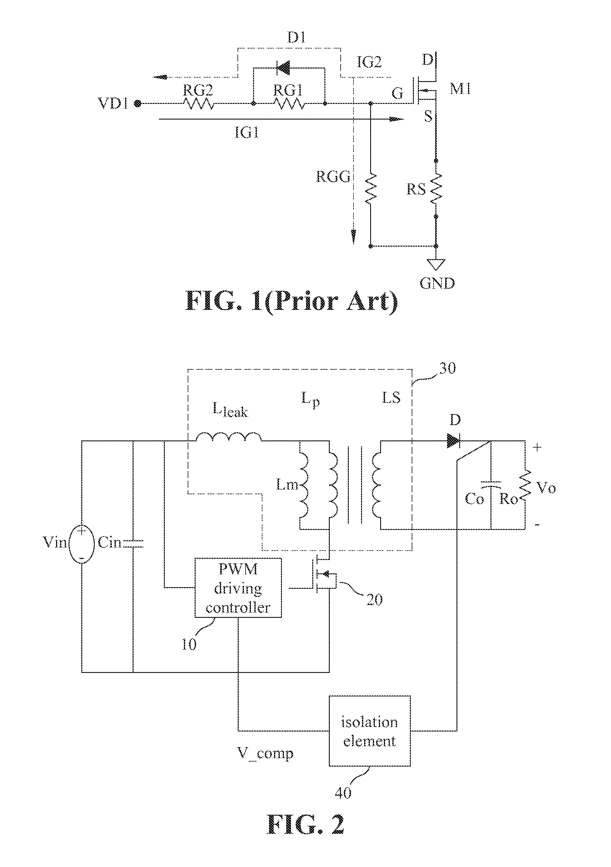
[0021]Please refer to FIG. 2 showing the power control apparatus with dynamical adjustment of driving capability according to one embodiment of the present invention. As shown in FIG. 2, the power control apparatus of the present invention comprises a pulsed width modulation (PWM) driving controller 10, a switch transistor 20, a transformer 30, an isolation element 40, an output diode D and an output capacitor Co for converting an input power with an input voltage Vin into an output power with an output voltage Vo, which is supplied to an external load Ro. The transformer 30, the PWM driving controller 10, the switch transistor 20 and the input power with the input voltage Vin are co...


PUM


Abstract

A power control apparatus with dynamical adjustment of driving capability for converting an input power into an output power includes a transformer, a switch transistor connected to the transformer, a pulsed width modulation (PWM) driving controller generating a PWM signal and connected to the switch transistor, an isolation element, an output diode and an output capacitor. The first side coil of the transformer and the switch transistor are connected to the input power, the second side coil of the transformer is connected to the output diode and further connected to the output capacitor and an external load. The isolation element converts the output power into a feedback signal providing the PWM driving controller to dynamically control the PWM driving signal through adjustment so as to implement the optimal turn-on current for the switch transistor. Therefore, electrical performance and conversion efficiency are greatly improved by reducing the switching loss.

Description

BACKGROUND OF THE INVENTION[0001]1. Field of the Invention[0002]The present invention generally relates to a power control apparatus, and more specifically to a power control apparatus for dynamically controlling the PWM driving signal through adjustment according to the operation state of the switch transistor in consideration of electromagnetic interference (EMI) and the switching loss so as to improve overall electrical performance and conversion efficiency.[0003]2. The Prior Arts[0004]Lately, power conversion efficiency has been a crucial topic for various electronic products, which need different voltage or current of electric power to normally operation. For instance, integrated circuits (ICs) need 5V or 3V, electric motors need 12V DC power, and lamps of LCD monitors need much higher voltage like 1150V. Thus, it is needed for power converters to meet the requirements of actual applications.[0005]In the prior arts, the scheme of switching power conversion is one of the primary...

Claims


Application Information

Patent Timeline
Patent Type & Authority Applications(United States)
IPC IPC(8): H02M3/335H02M1/44
CPCH02M1/44H02M3/33507H02M1/0029H02M1/0054Y02B70/10
Inventor LIN, SHU-CHIALIN, CHING-YUANLIN, CHIH FENGHSIEH, WEN-YUEH
Owner INNOTECH CO LTD
Why Eureka
Try Eureka