
Control apparatus for photovoltaic inverter

a technology of control apparatus and photovoltaic inverter, which is applied in the direction of electric variable regulation, process and machine control, instruments, etc., can solve the problems of affecting the operation of the control apparatus. achieve the effect of preventing the distortion of the output curren

Active Publication Date: 2016-05-19
TOSHIBA MITSUBISHI-ELECTRIC IND SYST CORP
View PDF4 Cites 9 Cited by
  • Summary
  • Abstract
  • Description
  • Claims
  • Application Information

AI Technical Summary

Benefits of technology

The present invention is a control apparatus for a photovoltaic inverter that prevents distortion of the output current due to an output voltage deficiency.

Problems solved by technology

However, disadvantageously, there are some cases in a photovoltaic inverter where, when there is an output voltage deficiency of the inverter due to variations in system voltage or the like, an output current of the inverter becomes distorted and flows backward (see Patent Literature 1).

Method used


Image

  • Control apparatus for photovoltaic inverter
  • Control apparatus for photovoltaic inverter
  • Control apparatus for photovoltaic inverter

Examples


first embodiment

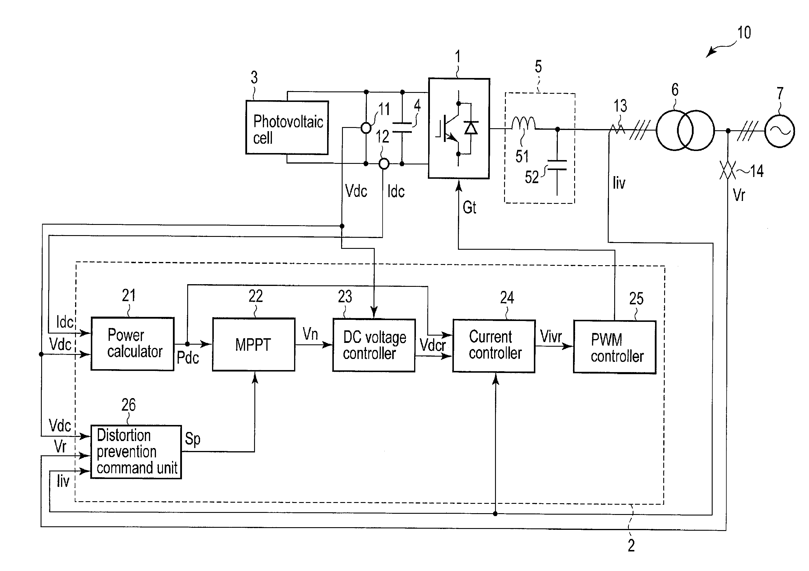
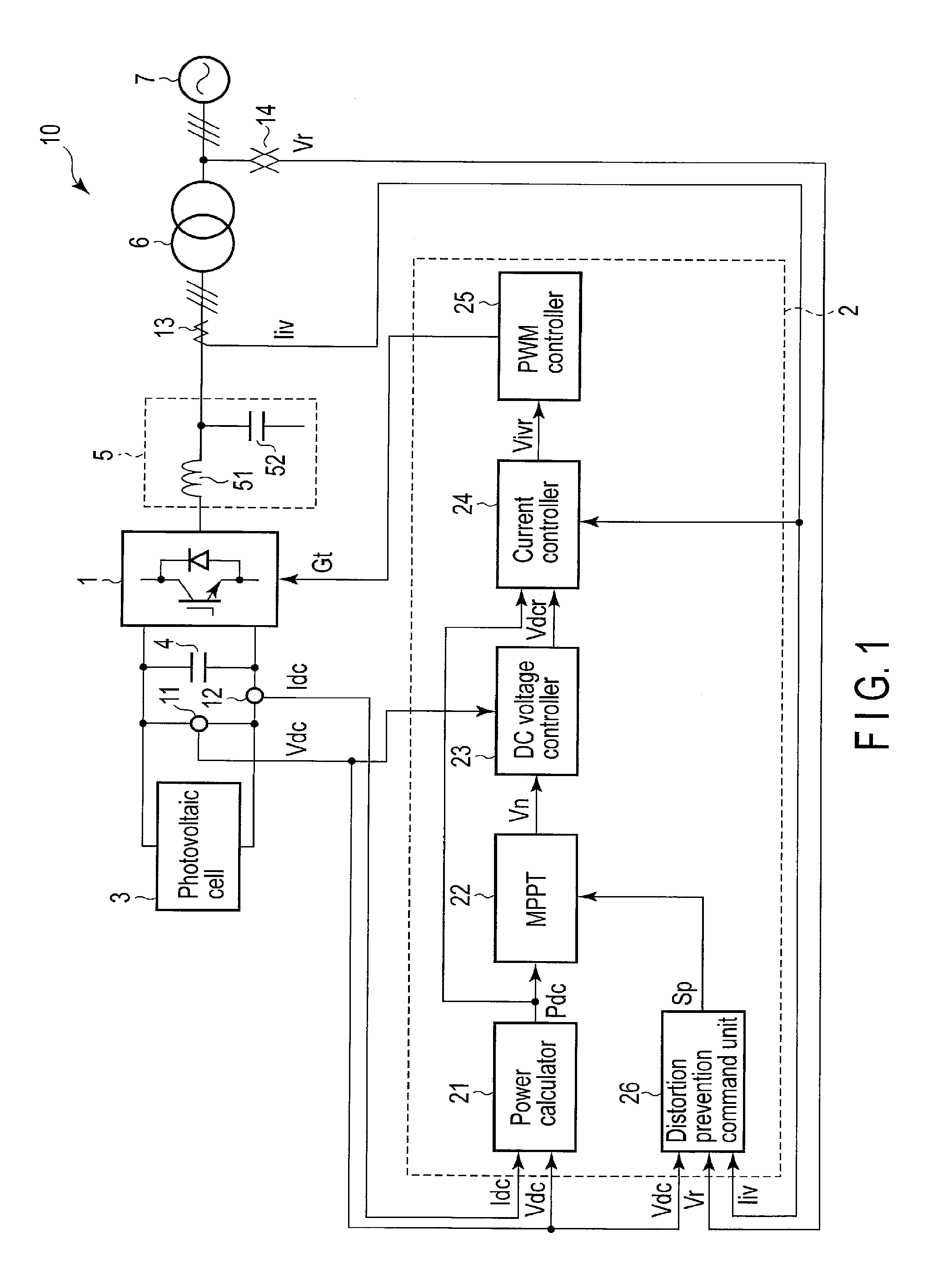
[0017]FIG. 1 a block diagram showing the structure of a photovoltaic power system 10 which adopts a control apparatus 2 for an inverter 1 according to a first embodiment of the present invention. Note that the same portions in the drawings will be denoted by the same reference numbers, the detailed explanations thereof will be omitted, and that different portions in the drawings will be mainly described.

[0018]The photovoltaic power system 10 includes the inverter 1, the control apparatus 2, a photovoltaic cell 3, a smoothing capacitor 4, an AC filter 5, an interconnection transformer 6, an AC power system 7, a DC voltage detector 11, a DC current detector 12, an AC current detector 13, and an AC voltage detector 14.

[0019]The photovoltaic cell 3 is a cell which generates power by light (sunlight). The photovoltaic cell 3 supplies the generated power to the inverter 1.

[0020]The inverter 1 converts the DC power supplied from the photovoltaic cell 3 into AC power synchronized with the A...

second embodiment

[0052]FIG. 4 is a block diagram showing the structure of a photovoltaic power system 10A which adopts a control apparatus 2A of the inverter 1 according to a second embodiment of the present invention.

[0053]The photovoltaic power system 10A includes a control apparatus 2A instead of the control apparatus 2 for the photovoltaic power system 10 according to the first embodiment shown in FIG. 1. The control apparatus 2A includes an MPPT 22A instead of the MPPT 22 of the control apparatus 2 according to the first embodiment, and a DC voltage controller 23A instead of the DC voltage controller 23 of the control apparatus 2 according to the first embodiment. The rest of the structure is the same as that of the first embodiment.

[0054]The MPPT 22A does not receive a control signal Sp from a distortion prevention command unit 26 and performs maximum power point tracking control at all times. The rest of the configuration of the MPPT 22A is similar to that of the MPPT 22 according to the firs...


PUM


Abstract

There is provided a control apparatus for a photovoltaic inverter. The control apparatus includes a system voltage detector, a DC voltage detector that detects a DC voltage applied to the inverter, an output voltage deficiency detector that detects an output voltage deficiency of the inverter based on the system voltage and the DC voltage, an output-current detector, an output-current distortion detector that detects distortion of the output current based on a harmonic included in the output current, a MPPT controller, and an output-current distortion controller that performs control to set the DC voltage applied to the inverter to a voltage at a power point less than a maximum power point when the output voltage deficiency is detected and the distortion of the output current is detected.

Description

CROSS REFERENCE TO RELATED APPLICATIONS[0001]This application is a Continuation Application of PCT Application No. PCT / JP2013 / 069886, filed Jul. 23, 2013, the entire contents of which are incorporated herein by reference.BACKGROUND OF THE INVENTION[0002]1. Field of the Invention[0003]The present invention relates generally to a control apparatus for a photovoltaic inverter.[0004]2. Description of the Related Art[0005]In general, photovoltaic power systems include inverters for interconnecting with alternating-current (AC) power systems. The inverters are configured to convert direct-current (DC) power generated by photovoltaic cells to AC power synchronized with the AC power systems and supply the AC power to the AC power systems.[0006]However, disadvantageously, there are some cases in a photovoltaic inverter where, when there is an output voltage deficiency of the inverter due to variations in system voltage or the like, an output current of the inverter becomes distorted and flow...

Claims


Application Information

Patent Timeline
Patent Type & Authority Applications(United States)
IPC IPC(8): H02M7/537
CPCH02M7/537H02J2300/26H02J3/381Y02E10/56Y02E40/20H02J3/1842
Inventor MATSUOKA, YUJIFIGUEROA, RUBEN ALEXIS INZUNZAAMBO, TATSUAKI
Owner TOSHIBA MITSUBISHI-ELECTRIC IND SYST CORP
Learn More