Method for maxillary sinus floor elevation

a maxillary sinus and floor elevation technology, applied in the field of maxillary sinus floor elevation, can solve the problems of reducing the survival rate of patients, jeopardizing the stability of implants, and authors did not report differences in survival rate between, so as to increase the neo-osteogenic potential, minimize invasivity and complications, and expand the space available for neo-osteogenesis

Inactive Publication Date: 2016-05-26
FAVERO RICCARDO +4
View PDF1 Cites 0 Cited by
  • Summary
  • Abstract
  • Description
  • Claims
  • Application Information

AI Technical Summary

Benefits of technology

[0021]Advantageously the stent is so configured and located to create, after expansion, space available for neo osteogenesis and contact surface between bone and blood clot increasing neo osteogenic potential.
[0031]This technique contemplates first the elevation of a mucoperiosteal flap along the edentulous ridge. A median osteotomy along the ridge will be then performed by means of a vibrating sonic scalpel, up to the maxillary sinus floor. The Schneider membrane will subsequently be elevated in order to allow the positioning of the stent. The stent is characterized by shape memory features and it is made of nickel-titanium. The stent diameter is determined preoperatively by means of cone-beam CT. Its length can be modified intraoperatively. The stent will shift back to the original shape keeping the Schneider membrane elevated with a minimally-invasive approach and expanding the space available for neo-osteogenesis. The nickel-titanium mesh texture optimizes moreover the contact surface between bone and clot increasing the neo-osteogenic potential. The aim of our technique is to obtain grater quantity and quality of the newly formed bone minimizing invasivity and complications that affect current sinus lift techniques. 5 months after the procedure it will be possible to proceed with the traditional steps of implant and prosthetic rehabilitation.

Problems solved by technology

However, some authors did not report differences in survival rate between antrostomies covered or not by membranes (Tones Garcia-Denche et al.
This shrinkage may jeopardize the stability of the implant at the second surgical stage.

Method used


Image

  • Method for maxillary sinus floor elevation
  • Method for maxillary sinus floor elevation
  • Method for maxillary sinus floor elevation

Examples


Embodiment Construction

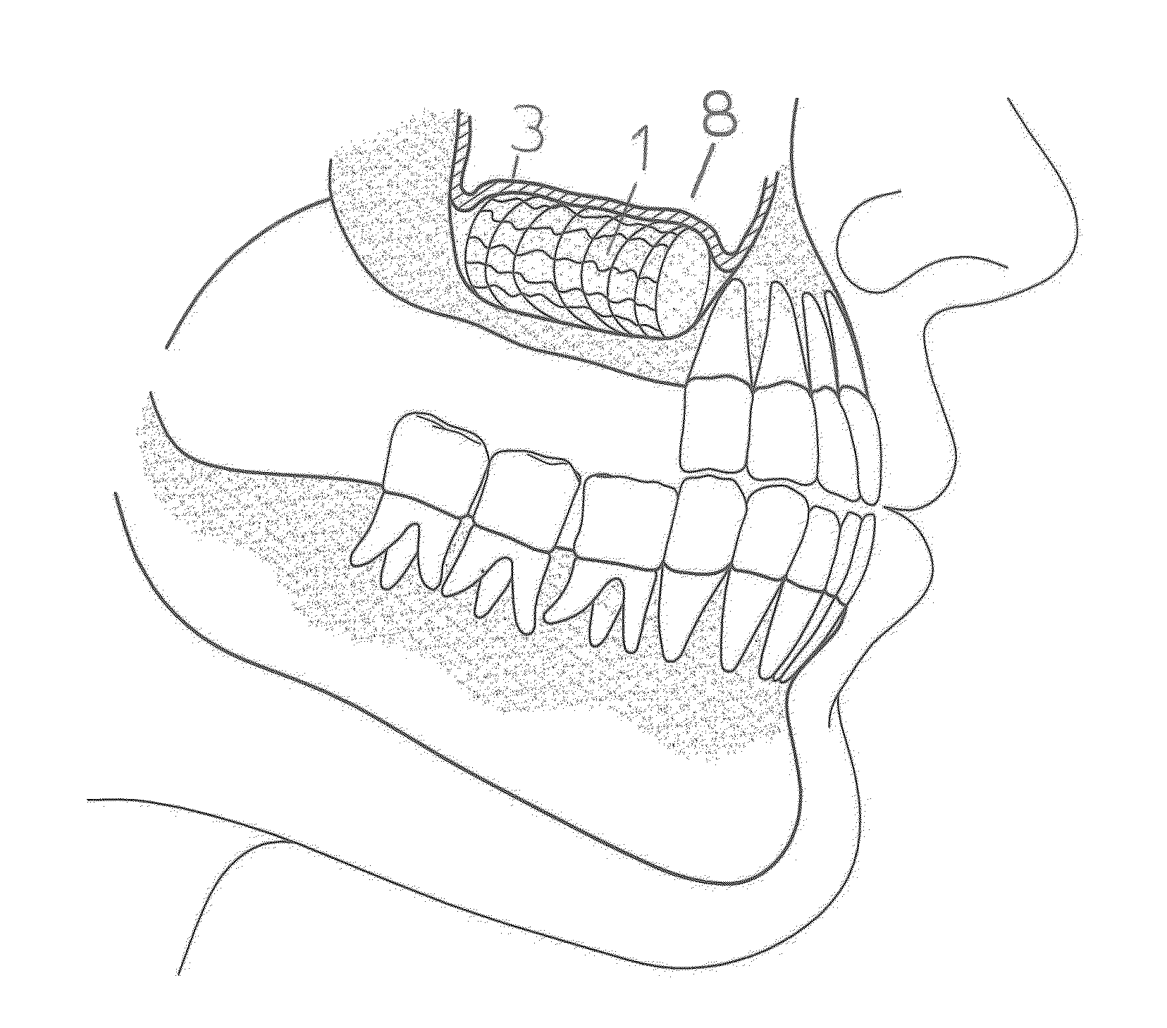
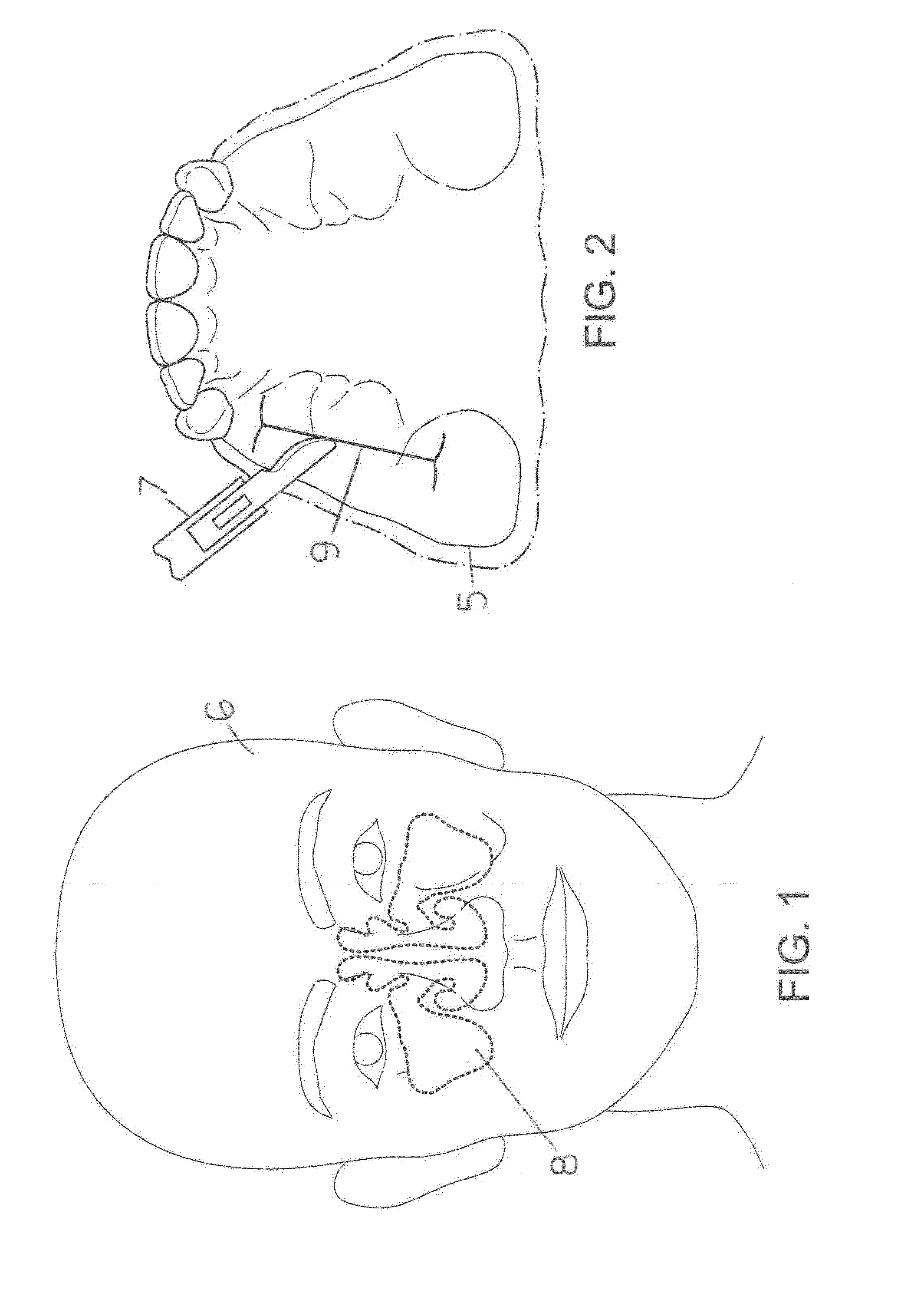
[0043]Anatomy of the maxillary sinus region will now be briefly described with reference to FIG. 1. FIG. 1 is a simplified, front view illustration of a human face 6, showing the position of the maxillary sinus 8.

[0044]FIG. 2 is a simplified occlusal view of the jaw 5 with distal edentulia, and a scalpel 7 A crestal incision of the mucosa 9 will be carried out.

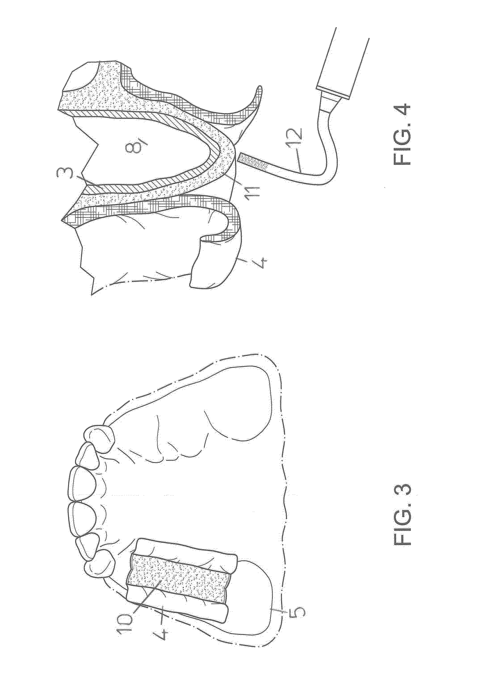
[0045]FIG. 3 is a simplified occlusal jaw 5 view, vestibular and palatal full thickness flaps 4 will be elevated and the bone is exposed 10.

[0046]FIG. 4 is a simplified, sectional illustration of the maxillary sinus 8, lateral maxillary walls 11, schneiderian membrane 3 and reflected mucoperiosteal flaps 4, The osteotomies will be performed by the use of a vibrating sonic handpiece 12 (Sonosurgery® TKD Calenzano Fi, Italy) carrying a straight 0.25 mm thick micro saw (SFS 102 Komet Gebr. Brasseler-GMBH, Lemgo 32631 Germany) and exercising a minimal pressure, similar to that of a pencil when writing (about 2-3 N max).

[0047]FIG. ...


PUM


Abstract

Devices and methods for placement of a self-expanding stent into the elevated region of a sinus floor are described. A mucoperiosteal flap is first elevated along the edentulous ridge. A median osteotomy along the ridge is then performed by means of a vibrating sonic scalpel, up to the maxillary sinus floor. The Schneider membrane is subsequently elevated in order to allow the positioning of the stent. The stent is characterized by shape memory features and is made of nickel-titanium. Stent diameter is determined preoperatively by means of cone-beam CT. Stent length can be modified intraoperatively. The stent shifts back to the original shape keeping the Schneider membrane elevated with a minimally invasive approach and expanding the space available for neo-osteogenesis. The nickel-titanium mesh texture of the stent optimizes the contact surface between bone and clot, increasing the neo-osteogenic potential. As a consequence, a greater quantity and quality of the newly formed bone is obtained, minimizing invasivity and complications that affect current sinus lift techniques.

Description

FIELD[0001]The present disclosure deals with a technique that can be used in dental implantology, in order to increase the vertical dimension of crestal bone elevating the Schneider membrane with a minimally invasive surgical approach and maximizing the quantity and quality of newly formed bone thanks to a completely biocompatible and inert Nitinol stent.DESCRIPTION OF RELATED ART[0002]Maxillary sinus floor elevation was introduced by Tatum (1977, 1986) and further developed by Boyne & James (1980). This surgical procedure was aimed at augmenting the bone volume in the posterior segments of the maxilla and it has been widely propagated in clinical implant therapy. However, in the absence of grafting material (e.g. Xu et al. 2004), or of a device (Cricchio et al. 2009, 2011; Johansson et al. 2012; Schweikert et al. 2012), or of implants (Ellegaard et al. 1997, Lundgren et al. 2004; Palma et al. 2006; Cricchio et al. 2013) placed simultaneously at the time of sinus floor elevation, th...

Claims


Application Information

Patent Timeline
Patent Type & Authority Applications(United States)
IPC IPC(8): A61C8/00
CPCA61C8/0092A61C8/0031A61C8/0033
Inventor FAVERO, RICCARDOFAVERO, VITTORIOBOTTICELLI, DANIELEFAVERO, LUCAFAVERO, LORENZO
Owner FAVERO RICCARDO
Why Eureka
Try Eureka