

Field emission device
a field emission and emission device technology, applied in gaseous cathodes, x-ray tubes, gas-filled discharge tubes, etc., can solve the problems of damage to the field emission emitter, the inability to control the quantity of emitted electrons and the acceleration energy of electrons independently,
- Summary
- Abstract
- Description
- Claims
- Application Information
AI Technical Summary
Benefits of technology
Problems solved by technology
Method used
Image

Examples
first embodiment
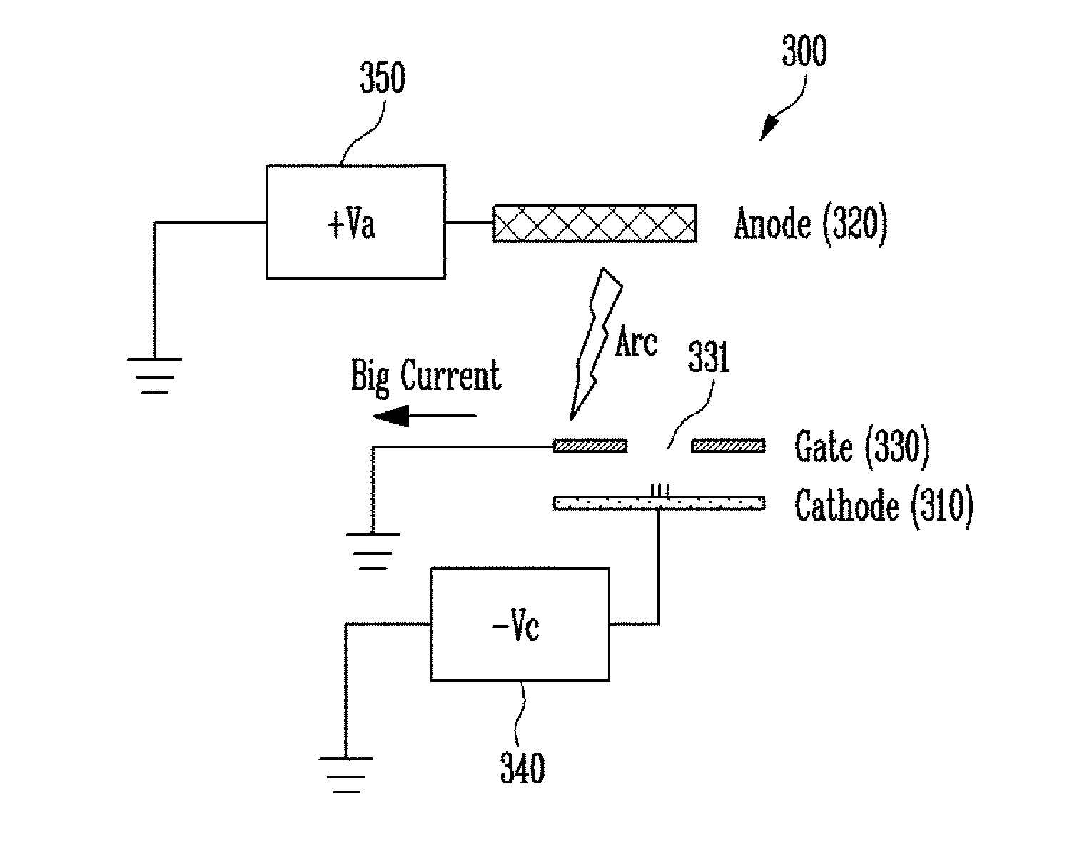
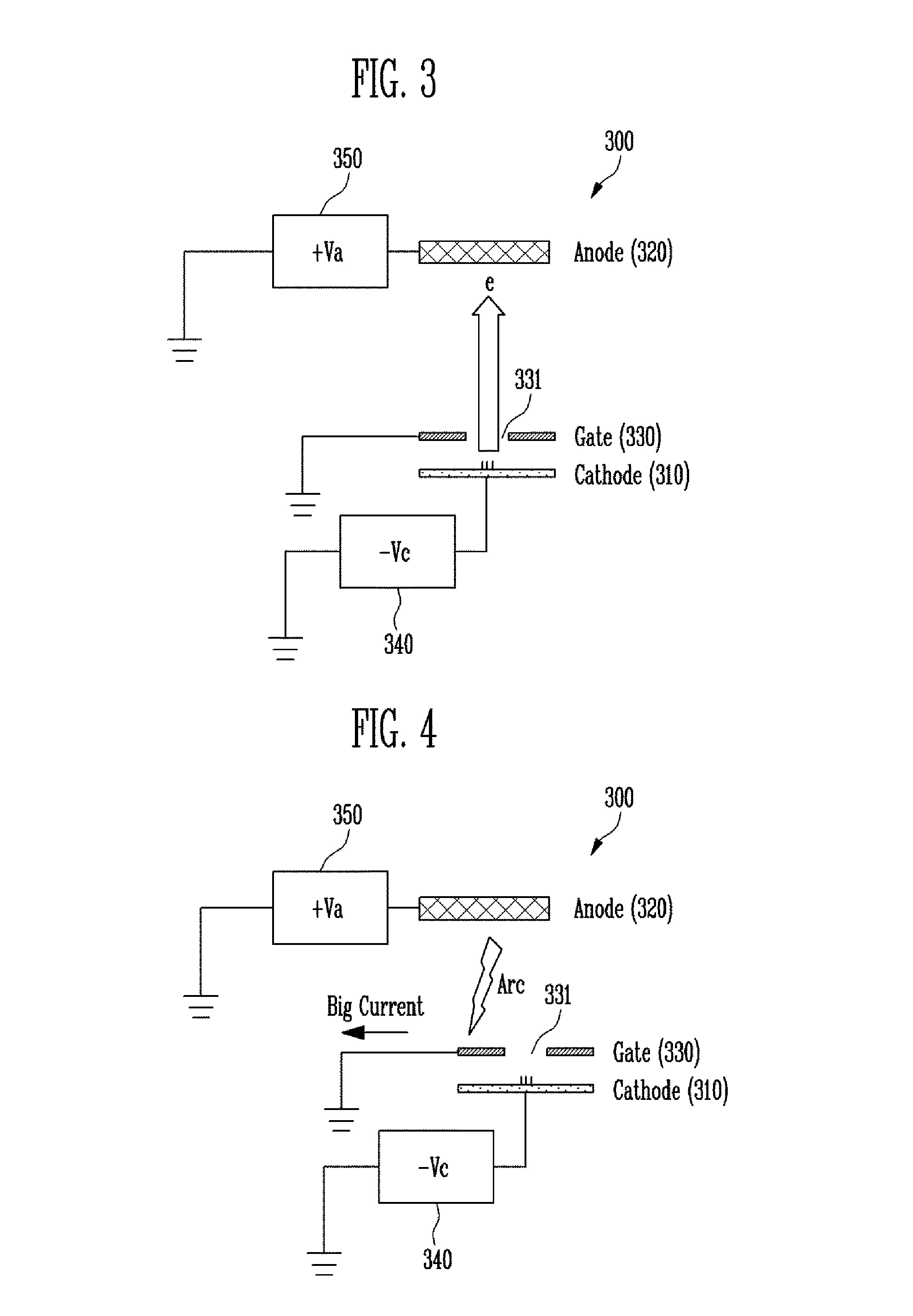
[0028]FIG. 3 is a view illustrating the configuration of a field emission device according to the present disclosure.
[0029]Referring to FIG. 3, the field emission device 300 according to the first embodiment of the present disclosure includes a cathode 310 which emits electrons, an anode 320 which emits rays when electrons emitted from the cathode 310 collide therewith, and a gate 330 which is formed to face the anode 320 and through which electrons emitted from the cathode 310 pass. The gate 330 may include an opening 331 to allow electrons emitted from the cathode 310 to pass through the gate 330. The anode 320 may include target material which enables the anode 320 to emit rays when electrons emitted from the cathode 310 collide with the anode 320.
[0030]In various embodiments of the present disclosure, the cathode 310 is connected to a negative power supply 340, the anode 320 is connected to a positive power supply 350, and the gate 330 is grounded. Hence, the cathode 310 has is ...
second embodiment
[0038]FIG. 6 is a view illustrating the configuration of a field emission device according to the present disclosure.
[0039]Referring to FIG. 6, the field emission device 600 according to the second embodiment of the present disclosure includes a cathode 610 which emits electrons, an anode 620 which emits rays when electrons emitted from the cathode 610 collide therewith, and a gate 630 which is formed to face the anode 620 and through which electrons emitted from the cathode 610 pass. The gate 630 may include an opening 631 to allow electrons emitted from the cathode 610 to pass through the gate 630. The anode 620 may include target material which enables the anode 620 to emit rays when electrons emitted from the cathode 610 collide with the anode 620.
[0040]In various embodiments of the present disclosure, the cathode 610 is connected to a negative power supply 640, the anode 620 is connected to a positive power supply 650, and the gate 630 is grounded. Hence, the cathode 610 has ne...
third embodiment
[0045]FIG. 9 is a view illustrating the configuration of a field emission device according to the present disclosure.
[0046]Referring to FIG. 9, the field emission device 900 according to a third embodiment of the present disclosure includes a cathode assembly 910 provided with a field emission electron gun 911 which emits electrons, and an anode 920 which includes target material 921 which enables the anode 320 to emit rays when electrons emitted from the cathode assembly 910 collide with the anode 920.
[0047]As shown in FIG. 10, in the case of an X-ray tube 1000 using a rotating anode 1020, a thermionic source 1011 of the cathode assembly 1010 functions as an electron emission source to emit X-rays. A field emission source can perform high-speed switching unlike that of the thermionic source 1011. Thus, if the field emission source substitutes for the thermionic source 1011, a high-speed pulse drive X-ray tube 1000 can be embodied. However, it is difficult to commercialize the field...
PUM
 Abstract
Description
Claims
Application Information