First stage turbine vane arrangement

Active Publication Date: 2016-06-02
ANSALDO ENERGIA SWITZERLAND AG
View PDF5 Cites 8 Cited by
  • Summary
  • Abstract
  • Description
  • Claims
  • Application Information

AI Technical Summary

Benefits of technology

[0003]An improved first stage turbine vane arrangement is suggested in orde

Problems solved by technology

However, radial, circumferential and axial relative movements of hot gas path sections relative to each other are difficult to seal and can lead to steps at the interface between the side

Method used


Image

  • First stage turbine vane arrangement
  • First stage turbine vane arrangement
  • First stage turbine vane arrangement

Examples


Example

[0043]The same or functionally identical elements are provided with the same designations below. The examples do not constitute any restriction of the invention to such arrangements.

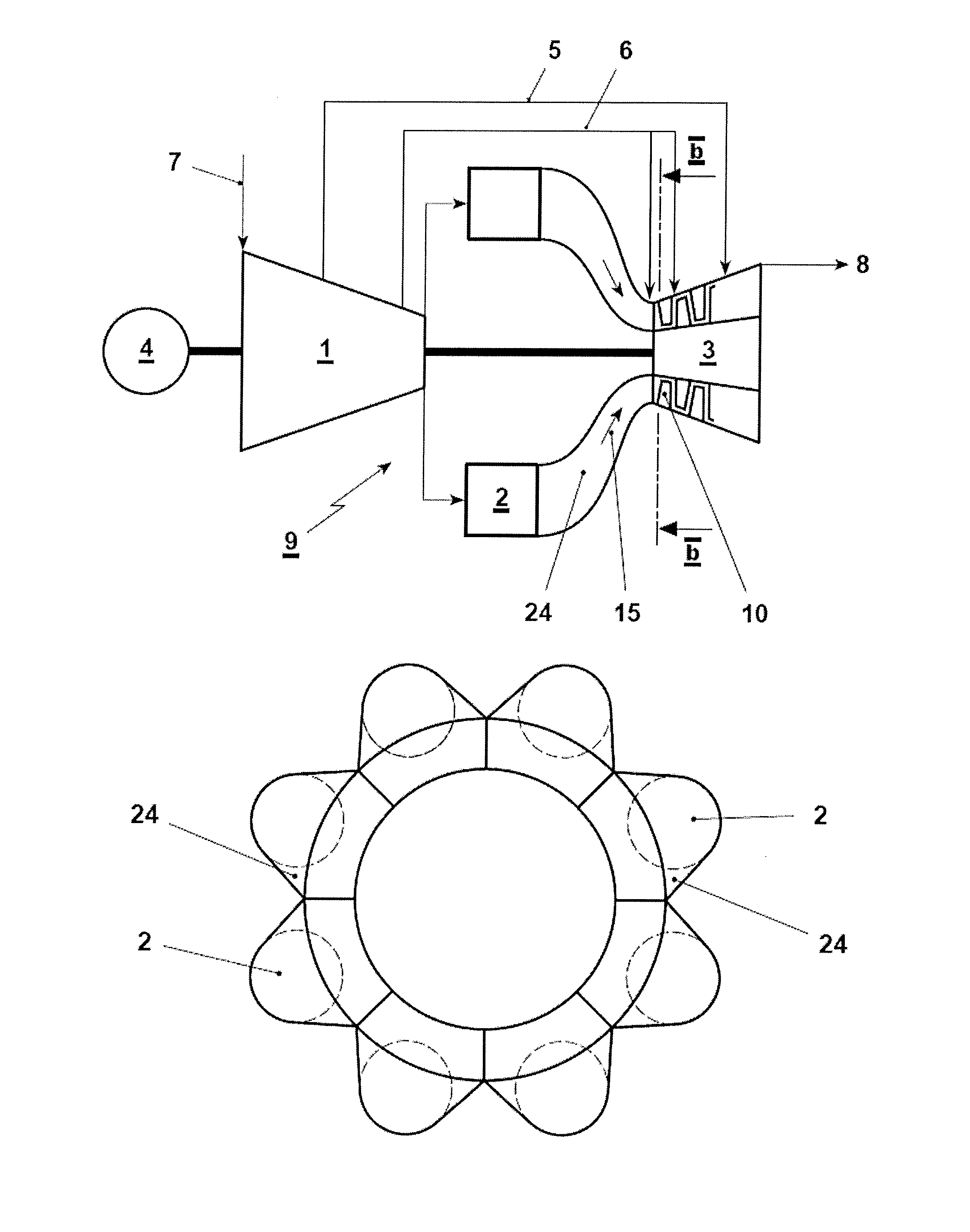
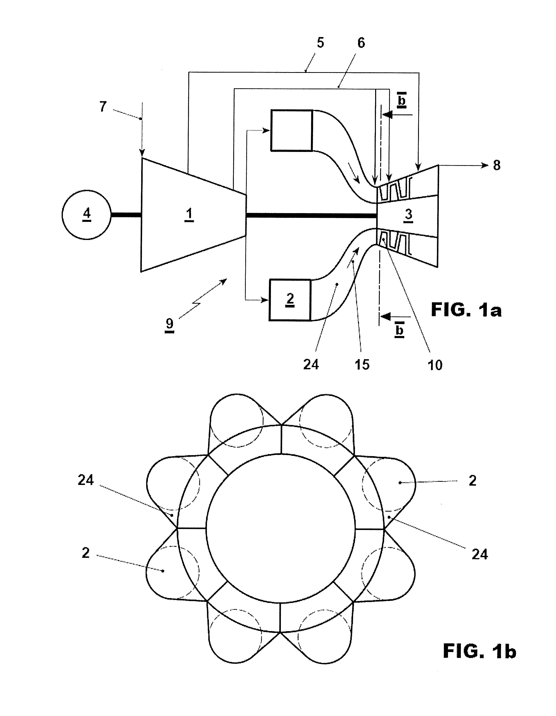
[0044]An exemplary arrangement is shown in Fig. la. The gas turbine 9 is supplied with compressor inlet gas 7. In the gas turbine 9 a compressor 1 is followed by a combustion chamber comprising a plurality of can combustors 2. Hot combustion gases are fed into a turbine 3 via a plurality of combustor transition pieces 24. The can combustors 2 and combustor transition pieces 24 form a hot gas flow path 15 leading to the turbine 3. The combustor transition pieces 24 connect the can combustors 2 of the combustion chamber with the first stage vane 10 of the turbine 3.

[0045]Cooling gas 5, 6 is branched off from the compressor 1 to cool the turbine 3, the combustor 2 (not shown) and a frame segment (not shown in FIG. 1). In this example the cooling systems for high pressure cooling gas 6 and low pressure cooli...


PUM


Abstract

The disclosure relates to a vane arrangement with a vane carrier, an array of rocking first stage vanes, and an array of frame segments for axially receiving aft ends of a combustor transition pieces. The frame segments comprise an I-beam with an upper horizontal element, a lower horizontal element, a vertical web, a radially outer fixation to the vane carrier, and an arm extending from the lower horizontal element in axial direction below the inner rim segment for supporting the inner platform of the vane and for sealing a gap between the inner platform and the lower horizontal element.
Besides the vane arrangement the disclosure relates to a method for assembly of such an arrangement as well as to a gas turbine comprising such a vane arrangement.

Description

TECHNICAL FIELD[0001]The disclosure relates to first stage vane arrangement for receiving a combustor transition piece which guides hot gases from the combustor to the turbine at the interface from a combustor to a turbine.BACKGROUND OF THE DISCLOSURE[0002]Gas turbines with can combustors are known from various applications in power plants. Typically a plurality of combustors is disposed in an annular array about the axis of the turbine. Hot combustion gases flow from each combustor through a respective transition piece into the first stage vane. In addition to relative movement, e.g. due to dynamic pulsing between these components, the transition pieces and first stage vane are made of different materials and are subjected to different temperatures during operation, thereby experiencing different degrees of thermal growth. Support frames which support and guide the transition piece at the turbine inlet have been proposed to allow such a “mismatch” at the interface of the transition...

Claims


Application Information

Patent Timeline
IPC IPC(8): F01D9/04
CPCF01D9/04F01D5/147F01D5/18F16J15/0887F01D9/023F01D11/005
Inventor GRAF, FRANKMATHEWS, HANS-CHRISTIANFLEURIOT, FABIENBENZ, URS
Owner ANSALDO ENERGIA SWITZERLAND AG
Why Eureka
Try Eureka