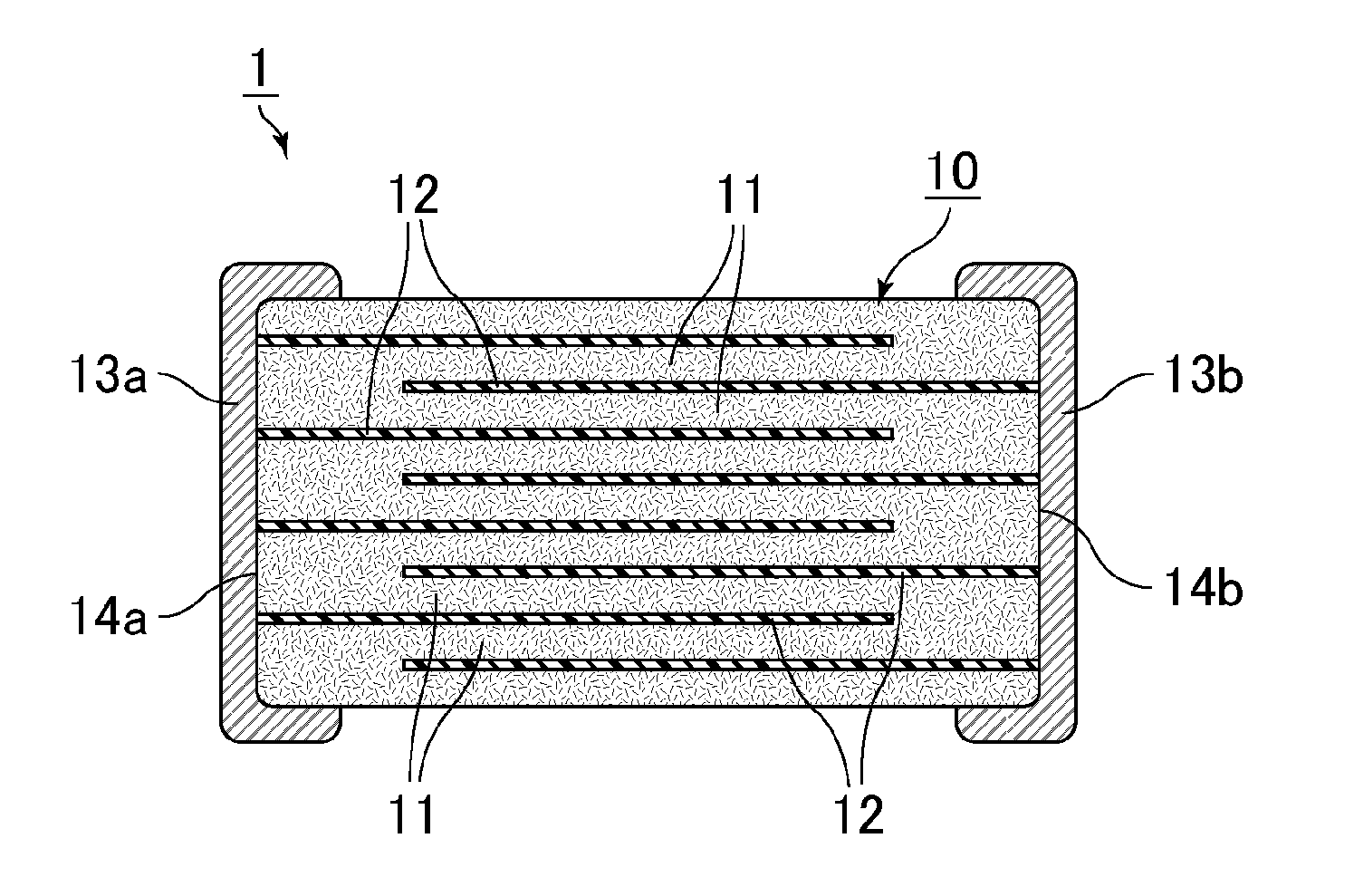
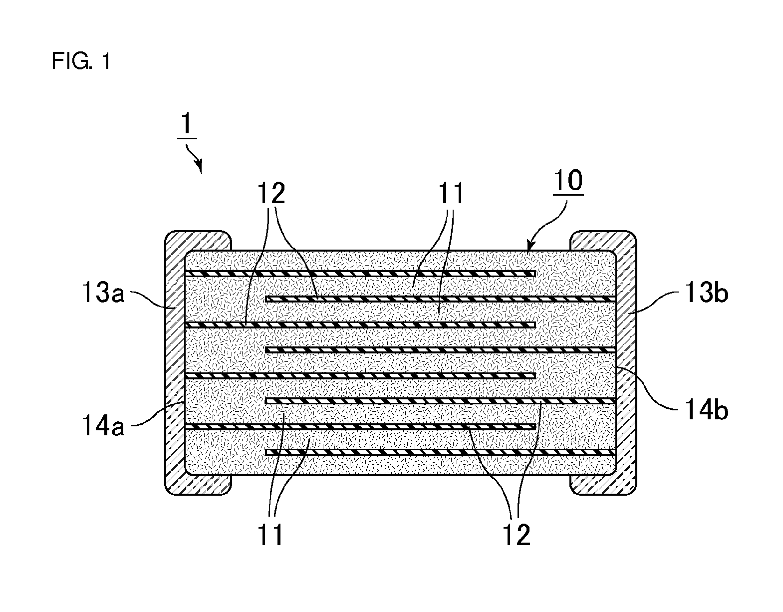
Multilayer ceramic capacitor and method for producing multilayer ceramic capacitor

a multi-layer ceramic capacitor and ceramic capacitor technology, applied in the direction of fixed capacitors, fixed capacitor electrodes, electrical equipment, etc., can solve the problems affecting the overall reliability of multi-layer ceramic capacitors, and achieve the effect of effectively preventing the movement of oxygen vacancies

Active Publication Date: 2016-06-02
MURATA MFG CO LTD
View PDF3 Cites 30 Cited by
  • Summary
  • Abstract
  • Description
  • Claims
  • Application Information

AI Technical Summary

Benefits of technology

[0058]The rare earth metals in this group more effectively prevent the movement of oxygen vacancies than the other R rare earth metals. The use of only R1 as the R or a combination of R1 a

Problems solved by technology

The swollen inner electrode layers form short circuits, and these short ci

Method used


Image

  • Multilayer ceramic capacitor and method for producing multilayer ceramic capacitor
  • Multilayer ceramic capacitor and method for producing multilayer ceramic capacitor

Examples


examples

[0123]The following describes some examples that disclose multilayer ceramic capacitors according to a preferred embodiment of the present invention in more detail. Note that these examples are not the only possible forms of various preferred embodiments of the present invention.

examples 1-1 to 1-15

and Comparative Examples 1-1 to 1-11

A) Preparation of a Ceramic Raw Material

[0124]Predetermined amounts of BaCO3 and TiO2 as starting materials were mixed using a ball mill. The mixture was heated at approximately 1150° C., yielding a perovskite compound Ba1.0070TiO3. The average particle diameter was approximately 0.15 μm, and the Ba / Ti ratio was approximately 1.0070.

[0125]The obtained Ba1.0070TiO3 (hereinafter also referred to as BT) was mixed with additional components for the Example or Comparative Example using a ball mill in accordance with the mixing formula in Table 1. The resulting mixture was dried, yielding a ceramic raw material.

[0126]The additional components were added in the form of CaCO3, MgO, R2O3, an oxide of M, and SiO2.

[0127]For use as the R2O3, powders of the following compounds were prepared: La2O3, Pr2O3, Eu2O3, Ho2O3, Er2O3, Lu2O3, Ce2O3, Yb2O3TM2O3, Tb2O3, Gd2O3, SM2O3, Nd2O3, Y2O3, and Dy2O3.

[0128]ICP analysis was performed on the obtained ceramic raw mater...

examples 2-1 to 2-11

A) Preparation of a Ceramic Raw Material

B) Production of Multilayer Ceramic Capacitors

[0150]As in Example 1-1, the compound BT used in Example 1-1 was mixed with additional components for the Example in accordance with the mixing formula in Table 2, and the obtained ceramic raw material was used to produce multilayer ceramic capacitors.

[0151]Example 2-1, in which the R included only Dy, an R1 element, is equivalent to Example 1-15.

[0152]In Examples 2-2 to 2-9, two sources of R were used. All of these Examples used one R1 element and one R2 element, with the proportion in parts by mole of R1 set as high as at least approximately four times larger than that of R2 (R1 / R2 approximately 4).

[0153]In Example 2-10, the R included only Ce, an R2 element.

[0154]In Example 2-11, two sources of R were used. The proportions of Dy, an R1 element, and Ce, an R2 element, were set in such a manner that R1 / R2

[0155]For all of these Examples, ICP analysis was performed on the ceramic ra...


PUM


Abstract

A multilayer ceramic capacitor includes a multilayer body including dielectric ceramic layers and inner electrode layers containing Ni and electrically connected to outer electrodes. The dielectric ceramic layers contain a Ba- and Ti-containing perovskite compound, Ca, Mg, R (at least one rare earth metal selected from La, Ce, Pr, Nd, Sm, Eu, Gd, Tb, Dy, Ho, Er, Tm, Yb, Lu, and Y), M (at least one selected from Zr, Mn, Co, Fe, Cr, Cu, Al, V, Mo, and W), and Si. The number of parts by mole of each element relative to Ti as 100 parts is as follows:
    • Ca, approximately 0.10 to 5.00 parts;
    • Mg, approximately 0.0010 to 0.0098 parts;
    • R in total, approximately 0.50 to 4.00 parts;
    • M in total, approximately 0.10 to 2.00 parts; and
    • Si, approximately 0.5 to 2.0 parts.

Description

BACKGROUND OF THE INVENTION[0001]1. Field of the Invention[0002]The present invention relates to a multilayer ceramic capacitor and a method for producing a multilayer ceramic capacitor.[0003]2. Description of the Related Art[0004]A multilayer ceramic capacitor includes a sintered ceramic body obtained through the firing of alternately stacked dielectric ceramic and inner electrode layers and outer electrodes formed on both end surfaces of the sintered ceramic body.[0005]With their high capacitance in a small size resulting from such a structure, multilayer ceramic capacitors have become widely used in many applications in the wake of the recent increase in the demand for mobile gear and other portable devices.[0006]Smaller and higher-capacitance multilayer ceramic capacitors are in demand. To meet this demand, researchers are trying to reduce the thickness of dielectric ceramic layers in a multilayer ceramic capacitor. Thinning the dielectric ceramic layers, however, leads to makin...

Claims


Application Information

Patent Timeline
IPC IPC(8): H01G4/12C04B35/468H01G4/012H01G4/30H01G4/008
CPCH01G4/1227H01G4/30C04B35/4682H01G4/008H01G4/012H01G4/1245H01B3/12C04B2235/3206C04B2235/3208C04B2235/3418B32B18/00C04B35/62685C04B35/634C04B35/638C04B2235/3215C04B2235/3224C04B2235/3225C04B2235/3227C04B2235/3229C04B2235/3244C04B2235/5445C04B2235/6021C04B2235/6582C04B2235/6584C04B2235/6588C04B2237/346C04B2237/68C04B2237/704
Inventor SHIMADA, KOHEIISHIDA, KATSUYA
Owner MURATA MFG CO LTD
Why Eureka
Try Eureka