Apparatus and method of controlling combustion exhaust for regenerative heating furnace

a technology of combustion exhaust and regenerative heating furnace, which is applied in the field of apparatus and control of combustion exhaust for regenerative heating furnace, can solve the problems of unstable temperature or atmosphere inside the furnace, energy loss, energy loss, etc., and achieve the effect of saving energy used for heating furnaces and maximizing the efficiency of saving consumption energy

Inactive Publication Date: 2016-06-09
SAC
View PDF2 Cites 3 Cited by
  • Summary
  • Abstract
  • Description
  • Claims
  • Application Information

AI Technical Summary

Benefits of technology

[0028]According to embodiments of the present invention, about 100% of exhaust gas is used for heat exchange, a furnace pressure control system is also applied, and thus there are particular effects in that appropriate product quality can be maintained and the efficiency of saving consumption energy can be maximized.
[0029]Also, according to embodiments of the present invention, high temperature combustion exhaust gas (about 20%) which has been discharged to the air to control the pressure inside typical furnaces is used for storing heat and preheating combustion air, and thus there is a particular effect in that energy used for the heating furnace may be saved.

Problems solved by technology

The reason the control of the ambient pressure inside the furnace (furnace pressure) is required is that when the furnace pressure becomes a negative pressure, ambient air is introduced into the furnace and thus not only makes the temperature or the atmosphere inside the furnace unstable, but also causes an energy loss because the amount of the introduced air is excessive.
On the contrary, when the furnace pressure is a positive pressure, the gas inside the furnace leaks from a gap around a material loading gate to cause an energy loss and also causes damage to the furnace body.
, and thus cause an energy loss.
Also, typical techniques require a separate exhaust gas discharge duct to discharge about 20% of the combustion gas generated in combustion to the outside, and since the temperature of the combustion gas is high, there is a disadvantage in that a separate refractory for heat insulation inside the exhaust duct should be installed.

Method used


Image

  • Apparatus and method of controlling combustion exhaust for regenerative heating furnace
  • Apparatus and method of controlling combustion exhaust for regenerative heating furnace
  • Apparatus and method of controlling combustion exhaust for regenerative heating furnace

Examples


Embodiment Construction

[0033]Hereinafter, an apparatus and a method of controlling combustion exhaust for a regenerative heating furnace according to an embodiment of the present invention will be described in detail with reference to the accompanying drawings. Moreover, detailed descriptions related to well-known functions or configurations will be ruled out in order not to unnecessarily obscure subject matters of the present invention.

[0034]In embodiments, a heating furnace may be a heating furnace for heating a material to a forgeable temperature in a forged steel producing process. However, the heating furnace is not limited thereto, and may be other kinds of heating furnaces.

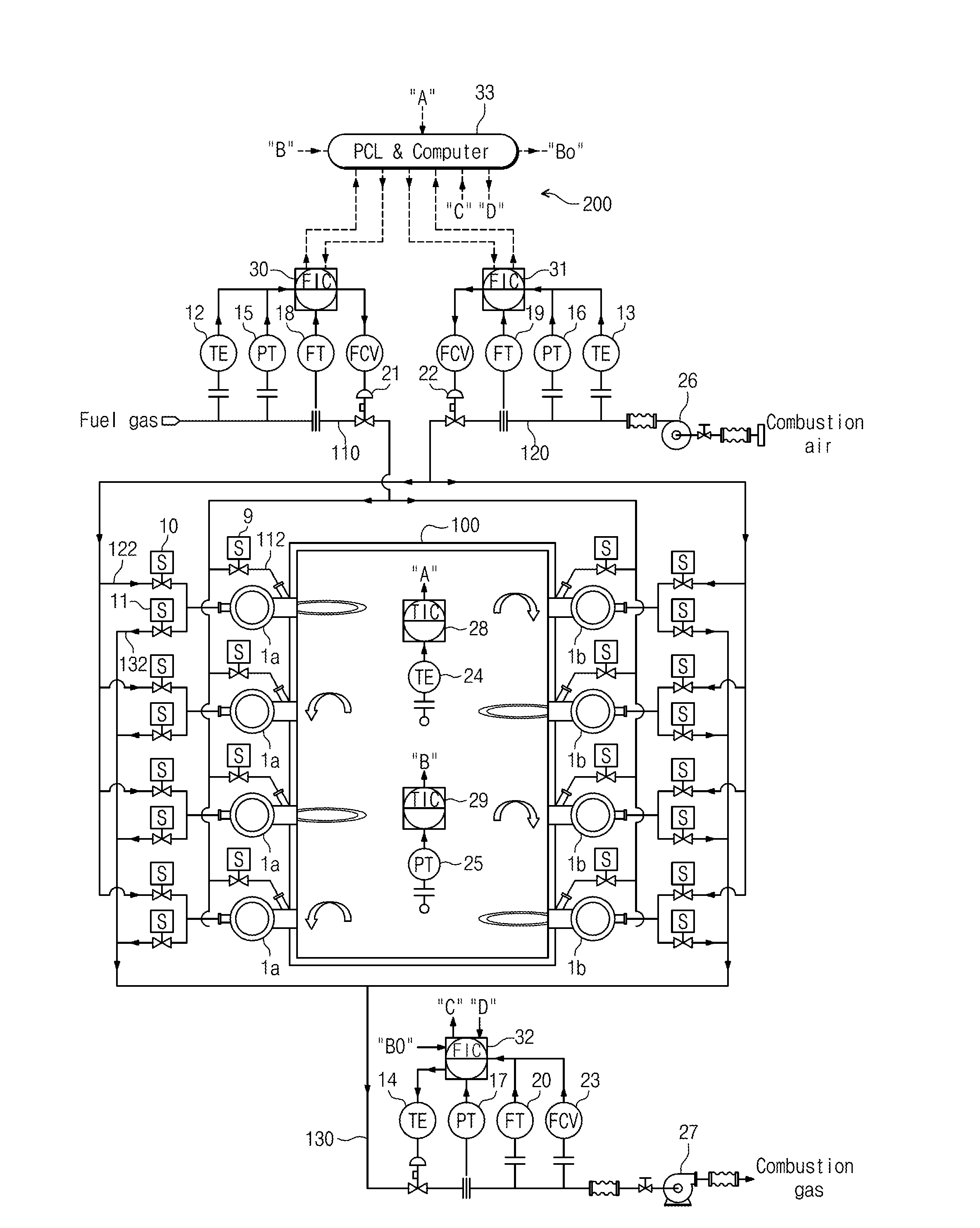
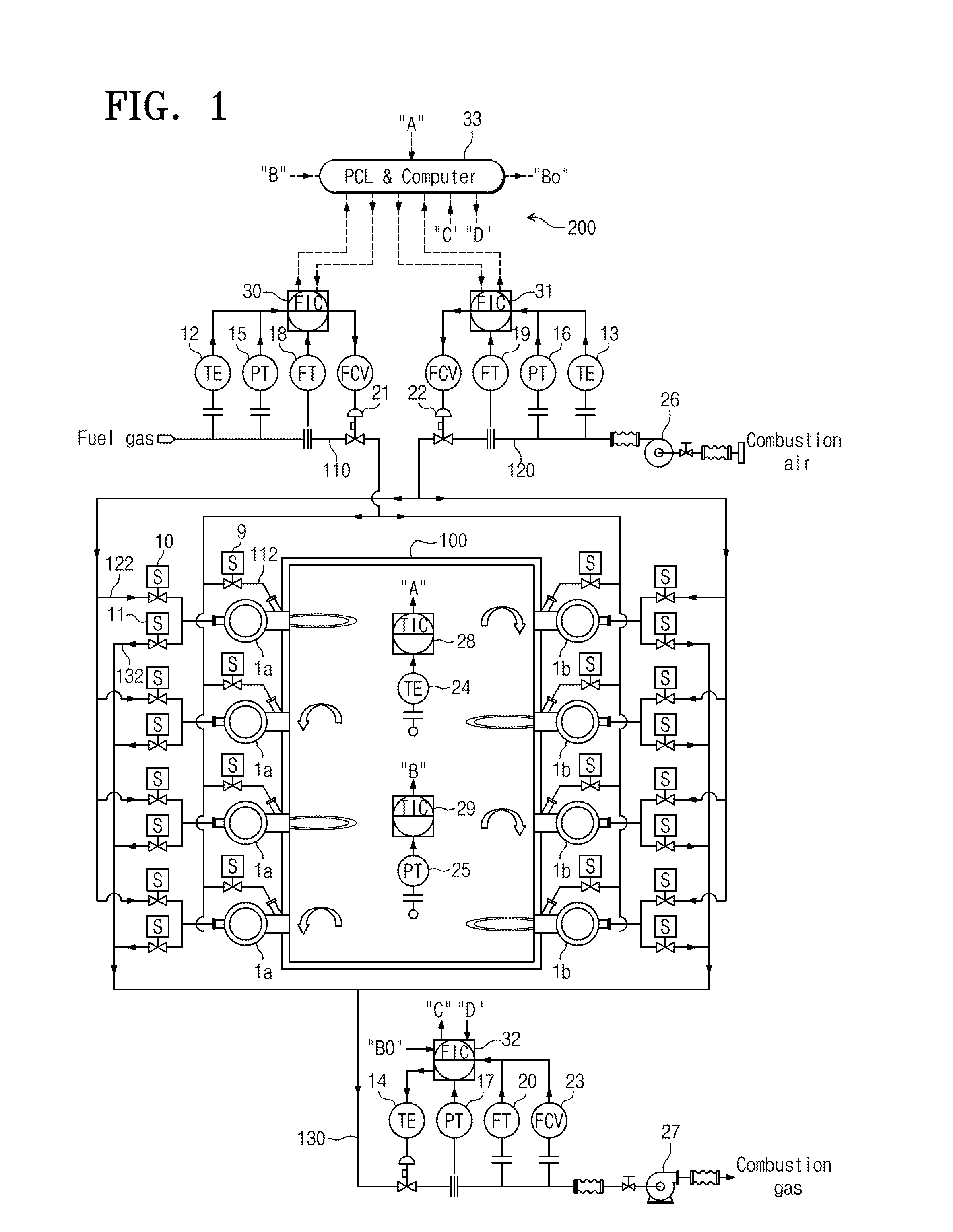
[0035]FIG. 1 is a schematic view illustrating an apparatus for controlling a regenerative heating furnace according to an embodiment of the present invention.

[0036]As illustrated in FIG. 1, a regenerative heating furnace 100 includes regenerative burners 1a and 1b installed to face each other on left and right sides thereof. Here...


PUM

PropertyMeasurementUnit
temperatureaaaaaaaaaa
combustionaaaaaaaaaa

Abstract

Provided is a method of controlling combustion of a regenerative heating furnace. The method controlled includes: a first step of sensing the temperature inside the furnace by a temperature sensor inside the heating furnace; a second step of receiving the measured temperature value inside the furnace, comparing the measured temperature value with a set reference temperature value, and outputting, to a sequence controller, an analog signal corresponding to a difference between the measured temperature value inside the furnace and the set reference temperature value; a third step of controlling combustion, and amounts of fuel, air, and discharged combustion gas of each of the burners by the sequence controller by a program set according to the outputted value in the second step; a fourth step of measuring the pressure inside the heating furnace due to combustion gas according to a combustion load; a fifth step of comparing the measured pressure value with the reference pressure, and outputting, the sequence controller, an analog signal corresponding to a difference between the measured pressure value and the reference pressure; and a sixth step of controlling, according to the outputted value of the fifth step, the discharge amount of combustion gas set in the third step by the sequence controller.

Description

TECHNICAL FIELD[0001]The present invention disclosed herein relates to a heating furnace for heating a material to a forgeable temperature in a forged steel producing process, and more particularly, to a control method and a control apparatus which control the amounts of fuel, combustion air, and combustion exhaust gas in a regenerative heating furnace using a regenerative combustion burner, so that the pressure inside the furnace due to combustion gas is appropriately controlled, and the entire exhaust gas is used for storing heat in a heat storage medium for heat exchange.BACKGROUND ART[0002]In general, in a steel production process, a heating furnace is used for heating a material to a target temperature, and a burner using a mixed gas as fuel is mostly used, and in recent years, there is an increasing trend of using a regenerative burner so as to save fuel.[0003]In all burners installed in typical heating furnaces, combustion is continuously performed, and exhaust gas generated ...

Claims


Application Information

Patent Timeline
Patent Type & Authority Applications(United States)
IPC IPC(8): F23N5/02F27D21/00F23L15/02
CPCF23N5/022F27D2019/0031F27D21/0014F23L15/02C21D1/52C21D9/00C21D11/00F23N5/00F27B17/0075F27D99/0033F27D2019/0018F27D2019/0028F27D2019/0087F27D2021/0007F23N2221/08F23N2225/04F23N2225/08Y02E20/34F27D19/00
Inventor JANG, BYOUNG LOKHAN, SEUNG HOONAN, MIN HWAN
Owner SAC
Why Eureka
Try Eureka