DC constant-speed brushless fan motor having wide voltage input

a brushless fan motor and constant-speed technology, applied in the direction of machines/engines, mechanical equipment, energy industry, etc., can solve the problems of imposing restrictions on the operation of the fan motor, the inability to perform hot plugging action when the motor is hot, and the inability to accept a wide range of input voltage in operation. , to achieve the effect of eliminating operation noise and saving consumed energy

Inactive Publication Date: 2017-02-23
HO TSUNG TE
View PDF0 Cites 0 Cited by
  • Summary
  • Abstract
  • Description
  • Claims
  • Application Information

AI Technical Summary

Benefits of technology

[0006]It is, therefore, an object of the present invention to provide a direct current (DC) constant-speed brushless fan motor, where a power supply unit may be used to supply a wide input voltage and convert the wide input voltage into an appropriate output power, so that the appropriate output power may be outputted to the brushless fan motor through a fan motor control unit and a fan motor drive unit. As such, the fan motor may reach a target rotational speed which may not be changed with the input voltage, with the efficacies of saved consumed energy and elimination of operation noise achieved simultaneously.

Problems solved by technology

However, the above DC brushless fan motor may not accept a wide range variation of the input voltage in operation since the rotational speed may alter with the variation of the input voltage.
In this case, a low voltage may not drive a high voltage motor and a high voltage may not drive a low voltage, imposing a restriction on the fan motor's operation.
Furthermore, a motor's hot plugging action may not be performed when an external system is operated.
When the ON / OFF period is employed to drive the fan motor, the fan motor may have a decreased efficiency.
Hence, the fan motor driven by the PWM ON / OFF period has a very low efficiency when it is operated under a low rotational speed.

Method used


Image

  • DC constant-speed brushless fan motor having wide voltage input
  • DC constant-speed brushless fan motor having wide voltage input
  • DC constant-speed brushless fan motor having wide voltage input

Examples


Embodiment Construction

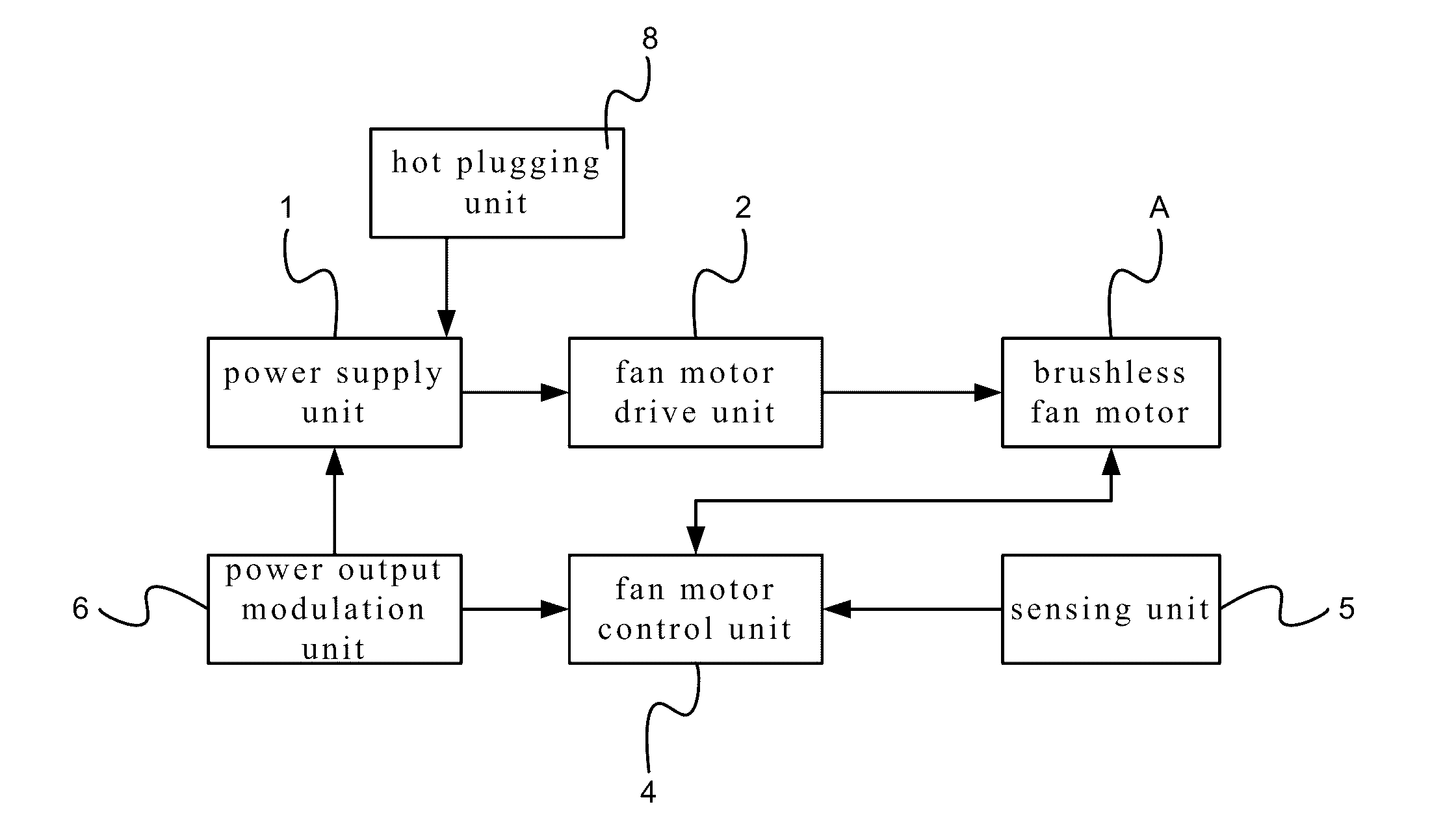
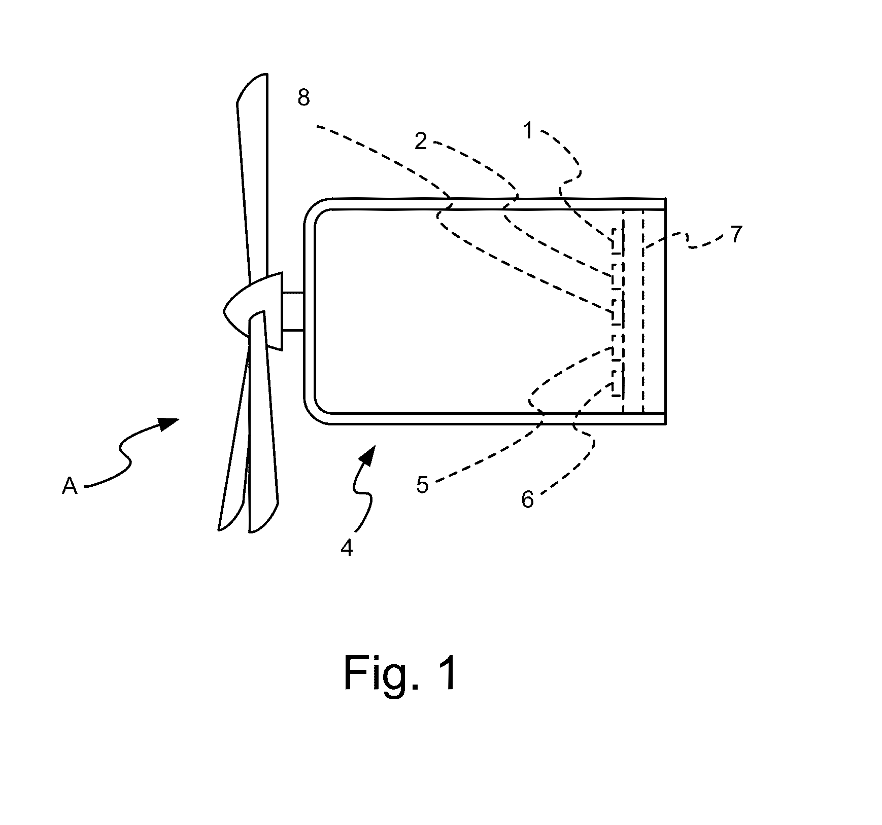
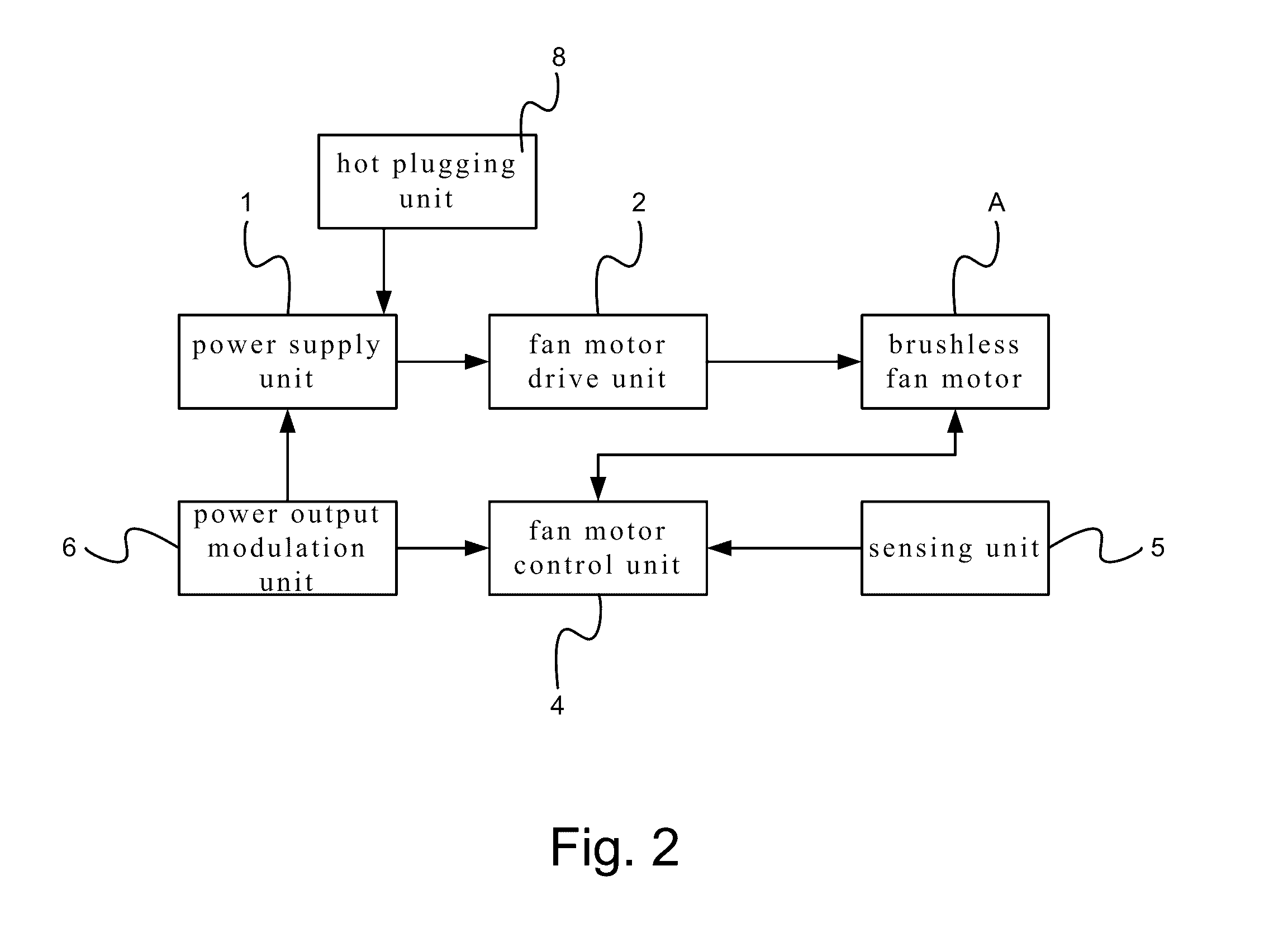
[0028]Referring to FIG. 1, FIG. 2, and FIG. 3 are a schematic diagram of a basic architecture according to the present invention, a schematic block diagram according to the present invention, FIG. 3 is a schematic diagram of a circuit according to the present invention, respectively.

[0029]As shown, the present invention is a direct current (DC) constant-speed fan motor having a wide input voltage, which comprises a power supply unit 1, a fan motor drive unit 2, a fan motor control unit 4, a sensing unit 5, and a power output modulation unit 6, which are all disposed on a circuit board 7. And, the circuit board 7 is disposed within the brushless fan motor A.

[0030]The power supply unit 1 includes an electromagnetic interference (EMI) filter circuit, which is used for filtering some conductive EMI. Further, the power supply unit 1 is a wide voltage input. In addition, the power supply unit 1 is further connected to a hot plugging unit 8.

[0031]The fan motor drive unit 2 is connected to ...


PUM


Abstract

A direct current (DC) constant-speed brushless fan motor having a wide voltage input, comprising a power supply unit; a fan motor driving unit, connected to the power supply unit; a fan motor, connected to the fan motor drive unit; a fan motor control unit, connected to the fan motor; and a sensing unit, connected to the fan motor control unit. As such, the power supply unit may be used to accept a wide voltage input and convert the wide input voltage into an appropriate output power, so that the appropriate output power may be outputted to the brushless fan motor through the fan motor control unit and the fan motor drive unit. As such, the fan motor may reach a target rotational speed which may not be changed with the input voltage, with the efficacies of saved consumed energy and elimination of operation noise achieved simultaneously.

Description

FIELD OF THE INVENTION[0001]The present invention relates to a direct current (DC) constant-speed brushless fan motor, and particularly to a DC constant-speed brushless fan motor, where a power supply unit may be used to accept a wide input voltage and convert the wide input voltage into an appropriate output power, so that the appropriate output power may be outputted to the brushless fan motor through a fan motor control unit and a fan motor drive unit. As such, the fan motor may reach a target rotational speed which may not be changed with the input voltage, with the efficacies of saved consumed energy and elimination of operation noise achieved simultaneously.DESCRIPTION OF THE RELATED ART[0002]In a currently available direct current (DC) fan motor, a fixed input voltage is connected and a fan motor drive unit, a fan motor control unit and a sensing unit are used to drive the fan motor to operate. In the case where the rotational speed is desired to changed, a modulation control...

Claims


Application Information

Patent Timeline
Patent Type & Authority Applications(United States)
IPC IPC(8): H02P27/08F04D19/00F04D27/00F04D25/06
CPCH02P27/08F04D27/004F04D19/002F04D25/0693H02P6/08Y02B30/70Y02P80/10
Inventor HO, TSUNG-TE
Owner HO TSUNG TE
Why Eureka
Try Eureka