Demountable optical connector for optoelectronic devices

a technology of optoelectronic devices and optical connectors, which is applied in the direction of optical elements, instruments, manufacturing tools, etc., can solve the problems of fiber connection, time-consuming process, and one of the most expensive components of photonic networks, and achieve the effect of increasing the stiffness of the interface, reducing the dependence on the bending stiffness of the connector, and adding to the cos

Inactive Publication Date: 2016-06-09
SENKO ADVANCED COMPONENTS
View PDF13 Cites 43 Cited by
  • Summary
  • Abstract
  • Description
  • Claims
  • Application Information

AI Technical Summary

Benefits of technology

[0011]In accordance with one embodiment of the present invention, the foundation is initially attached to a support (e.g., housing) of the opto-electronic device (e.g., PIC). This foundation can be aligned to electro-optical elements in the device. The foundation may be permanently attached with respect to the opto-electronic device. The optical bench (e.g., supporting an optical fiber) can be removably attached to the foundation, via a ‘separable’ or ‘demountable’ or ‘detachable’ action that accurately optically aligns the optical components / elements in the optical bench to the opto-electronic device along a desired optical path. In accordance with the present invention, a detachable connector supports or is part of the optical bench. In order to maintain optical alignment for each connect and disconnect and reconnect, this connector needs to be precisely and accurately aligned to the foundation. In one embodiment of the present invention, the connector and foundation are aligned with one another using a passive mechanical alignment constructed from geometric features on the two bodies.
[0012]In a further embodiment, the present invention provides a structure and method for this passive alignment using kinematic coupling, quasi-kinematic coupling, or elastic-averaging couplings. One approach is a kinematic coupling with six points of contact between the connector and the foundation. Six points is the minimum necessary for rigid body static equilibrium and consequently provides a deterministic and repeatable alignment between the bodies. An alternate approach that provides additional stiffness at the interface and reduces the dependence on the bending stiffness of the connector is to use a quasi-kinematic approach which adds additional contact points or replaces a contact point with a contact line. Additional contact points and contact lines increases the stiffness of the interface with modest reductions in the repeatability. In this embodiment, the contact is spread over larger area between the two bodies and stiffens the bending modes of the connector. A third embodiment maximizes the stiffness of the interface using many, perhaps hundreds or thousands, of contact points or small surfaces (e.g. tetrahedral) that are spread over as much area as possible. This requires accurate location of the mating surfaces and more stringent tolerances on the shape and size of the surfaces. However, this can be accomplished with ultra-high precision stamping.
[0013]In another aspect of the present invention, the passive alignment features on the foundation and connector can be integrally / simultaneous formed by precision stamping, which allows the components to be produced economically in high or small volumes, while improving tolerance, manufacturability, ease of use, functionality and reliability. Further, either or both of the foundation and the connector (e.g., a micro optical bench (MOB)) can be precisely formed by high-precision stamping. The foundation and / or optical bench components should be made of a stampable materials like ductile metals such as Kovar, Invar, stainless steel, aluminum. The optical bench and foundation should both have similar coefficients of thermal expansion (CTEs), so that misalignment does not occur during temperature cycles and stress / strains are not generated.

Problems solved by technology

One of the most expensive components within photonic networks are the fiber-optic connectors.
This is challenging and so much optical fibers are aligned to elements on the PICs using an active alignment approach in which the position and orientation of the optical fiber(s) is adjusted by machinery until the amount of light transferred between the fiber and PIC is maximized.
This is a time consuming process that is generally done after the PIC is diced from the wafer and mounted within a package.
In other words, optical fiber is not removably attachable to the PIC, and the fiber connection, and separation would be destructive and not reversible (i.e., not reconnectable).
Manufacturers of integrated circuits and PICs often have expensive capital equipment capable of sub-micron alignment (e.g. wafer probers and handlers for testing integrated circuits), whereas companies that package chips generally have less capable machinery (typically several micron alignment tolerances which is not adequate for single-mode devices) and often use manual operations.
However, it is impractical to permanently attach optical fibers to PICs prior to dicing since the optical fibers would become tangled, would be in the way during the dicing operations and packaging procedures, and are practically impossible to manage when the PICs are pick-and-placed onto printed circuit boards and then soldered to the PCBs at high temperatures.
Second, they are not dimensionally stable and can change size and shape especially when subjected to elevated temperatures such as those found in computing and networking hardware.
Therefore, temperature cycles cause misalignment between the optical fibers and the devices on the PIC.
In some cases, the polymers cannot withstand the processing temperatures used while soldering PICs onto printed circuit boards.

Method used


Image

  • Demountable optical connector for optoelectronic devices
  • Demountable optical connector for optoelectronic devices
  • Demountable optical connector for optoelectronic devices

Examples


Embodiment Construction

[0019]This invention is described below in reference to various embodiments with reference to the figures. While this invention is described in terms of the best mode for achieving this invention's objectives, it will be appreciated by those skilled in the art that variations may be accomplished in view of these teachings without deviating from the spirit or scope of the invention.

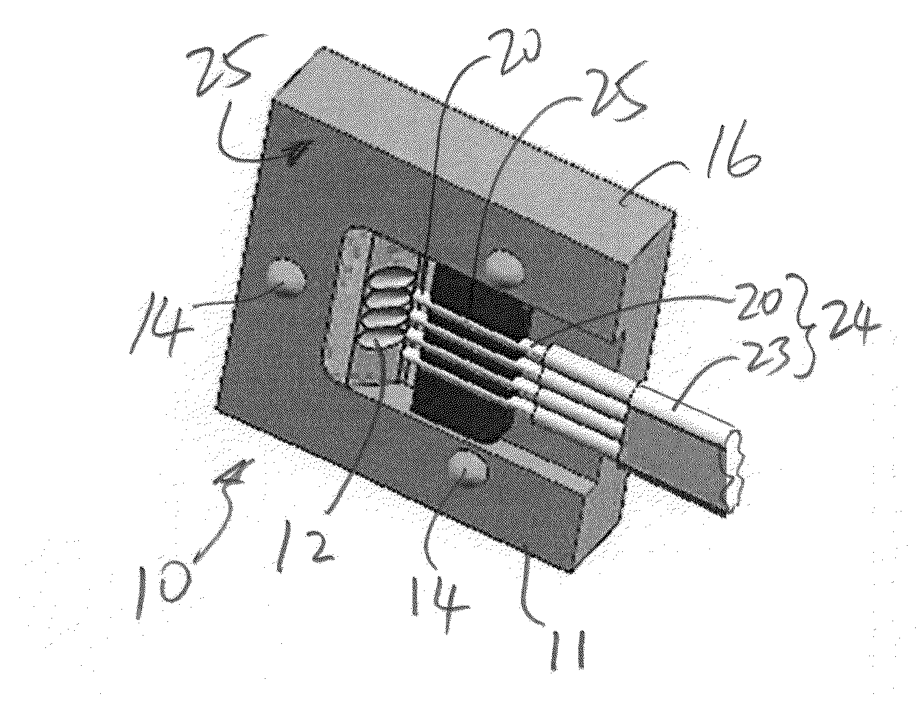
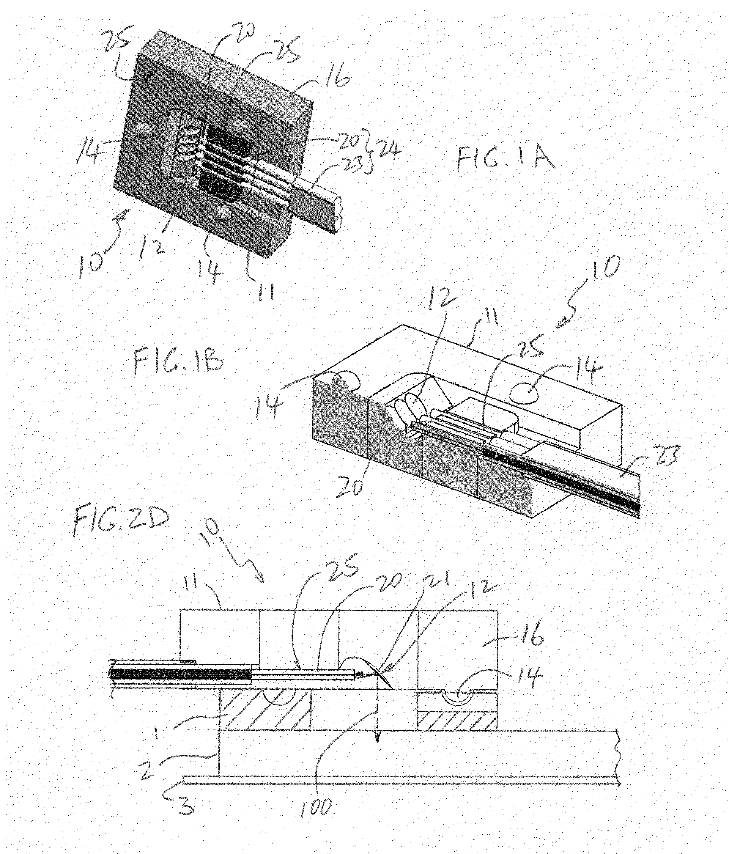
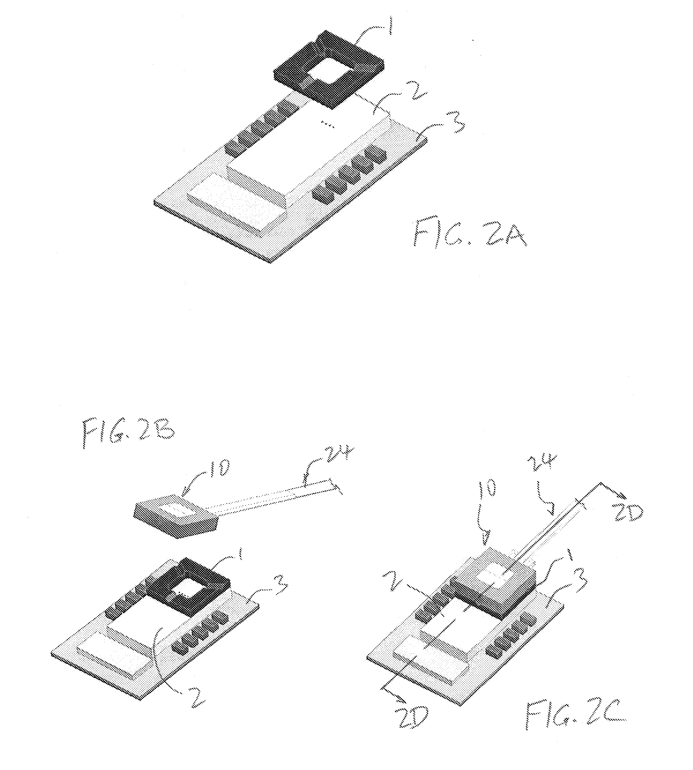
[0020]The present invention provides a novel approach to coupling light between an optical bench (e.g., supporting an optical fiber) and an opto-electronic device (e.g., grating coupler of a photonic integrated circuits (PIC)). The novel connection includes a foundation and a connector that is configured and structured to be removably attachable for reconnection to the foundation in alignment therewith.

[0021]The concept of the present invention will be discussed with reference to an example of a PIC as an opto-electronic device, and an optical bench as an optical coupling device (connector) for use to opti...


PUM

PropertyMeasurementUnit
optical pathaaaaaaaaaa
connection structureaaaaaaaaaa
elasticaaaaaaaaaa

Abstract

A reconnectable connection between an optical bench supporting an optical fiber and a photonic integrated circuit (PIC), which a foundation and a connector that is configured and structured to be removably attachable for reconnection to the foundation in alignment therewith. The foundation can be aligned to electro-optical elements in the PIC. The foundation may be permanently attached with respect to the opto-electronic device. The optical bench can be removably attached to the foundation. Alignment between the foundation and the connector is achieved by kinematic coupling, quasi-kinematic coupling, or elastic-averaging coupling.

Description

PRIORITY CLAIM[0001]This application claims the priority of U.S. Provisional Patent Application No. 61 / 994,097 filed on May 15, 2014. This application is fully incorporated by reference as if fully set forth herein. All publications noted below are fully incorporated by reference as if fully set forth herein.BACKGROUND OF THE INVENTION[0002]1. Field of the Invention[0003]The present invention relates to coupling of light into and out of optoelectronic devices (e.g., photonic integrated circuits (PICs)), and more particular to the optical connection of optical fibers to PICs.[0004]2. Description of Related Art[0005]Photonic integrated circuits integrate multiple electro-optical devices such as lasers, photodiodes, modulators, and waveguides into a single chip. It is necessary for these PICs to have optical connections to other PICs, often in the form an organized network of optical signal communication. The connection distances may range from a several millimeters in the case of chip...

Claims


Application Information

Patent Timeline
Patent Type & Authority Applications(United States)
IPC IPC(8): G02B6/42G02B6/30
CPCG02B6/4231G02B6/30G02B6/4214G02B6/4292G02B6/4249G02B6/423
Inventor LI, SHUHEVALLANCE, ROBERT RYAN
Owner SENKO ADVANCED COMPONENTS
Why Eureka
Try Eureka