System comprising a sound attenuating panel

a technology of attenuating panel and sound, which is applied in the direction of instruments, lighting and heating apparatus, semiconductor devices for light sources, etc., can solve the problems of static, not adapting to changes, and requiring a lot of effort, so as to reduce perceived transparency, reduce perceived transparency, and protect privacy

Inactive Publication Date: 2016-06-09
SIGNIFY HLDG BV
View PDF0 Cites 11 Cited by
  • Summary
  • Abstract
  • Description
  • Claims
  • Application Information

AI Technical Summary

Benefits of technology

[0032]The transparent unit part may especially comprise outcoupling structures, at an exit surface, and / or embedded in the material that is transparent for visible light. Herein, the material that is transparent for visible light is also indicated as transparent material. This light can be used to assist a person in doing activities and / or in generating a specific atmosphere, and / or can be used to crate privacy. When the light of the light source is coupled into the unit part, light will be coupled out from the transparent unit part. In this way, the perceived transparency is reduced, as a spectator will now not see, or see less, objects behind the transparent unit part, but will see the light coupled out in the direction of (amongst others) the spectator. The fact that a spectator will especially see the light and not an object behind the transparent unit, while the transparency may not really be affected, is indicated as (reduction of) perceived transparency. Hence, in a specific embodiment, the invention also provides a system wherein sound attenuating panel comprises a sound attenuating unit, wherein the sound attenuating unit comprises a transparent unit part comprising a material that is transparent for visible light, wherein the sound attenuating panel further comprises a light source that is configured to provide light into the transparent unit part, wherein the transparent unit part has light guiding properties and wherein the transparent unit part is configured to allow transmission of visible light from a first face of the sound attenuating panel to a second face, and wherein the transparent unit part and light source are configured (to be able) to provide light escaping to both faces of the sound attenuating panel.
[0033]Above, the principle of controlling the sound attenuating properties is described. Amongst others, this above principle is applied in this invention, optional also in combination with lighting properties, as for instance the acoustic material may also have light guiding properties (wave guiding properties). Hence, the principle of controlling acoustic properties by modulating cavities (like spaces, holes, pores, etc.) in a material may also be applied to a light divider concept to improve its acoustic properties since it is currently made from a hard polymer or glass like material into which light is coupled. Once the light has been coupled into the material the users will find it harder to see through the divider, thus enhancing the feeling of privacy. When the user turns on the light to increase the feeling of privacy, the absorption of sound should also increase since it is most likely that the user desires to work in a quiet context. At this point, the sound absorbing material / screens that may be located in the area or on the light dividing screens could change shape to absorb more of the sound. When the user turns off the light, the transparent part of the panel may also be perceived as transparent (as the light is not changing the perception anymore) and so the user or other people can see through the transparent part. At both faces of the acoustic panel, they can see each other and perhaps once they begin to talk. The sound absorbing material may be flexed to open up the fibers or openings to enable the passage of sound and ease conversation.

Problems solved by technology

These measures can be costly and require a lot of effort.
A big disadvantage of existing desk divider solutions is that they are static and do not adapt to changes in the open office environment.

Method used


Image

  • System comprising a sound attenuating panel
  • System comprising a sound attenuating panel
  • System comprising a sound attenuating panel

Examples


Embodiment Construction

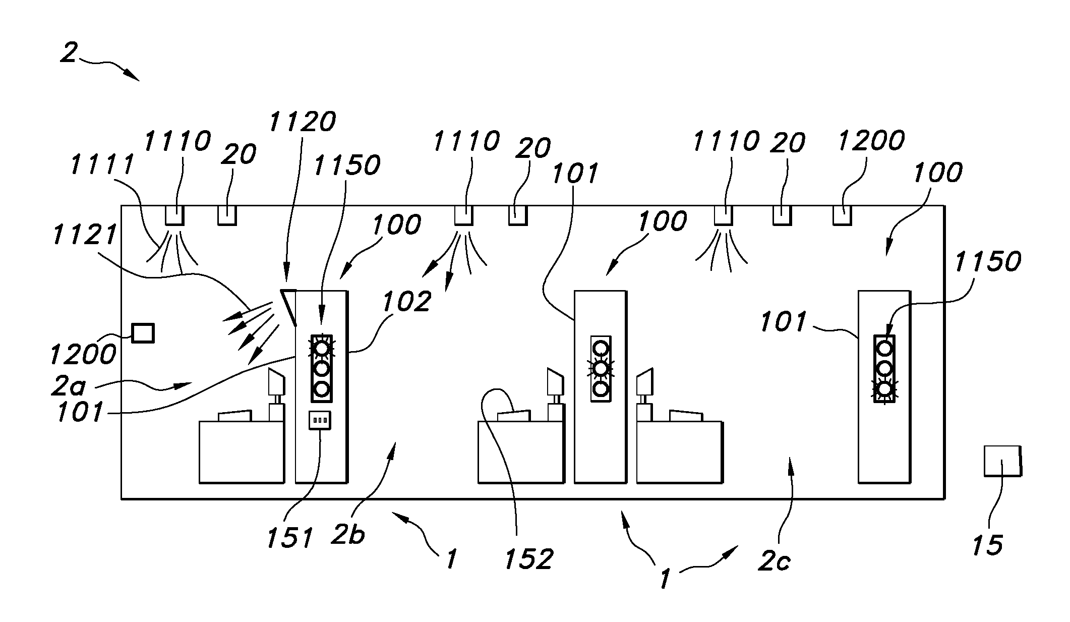
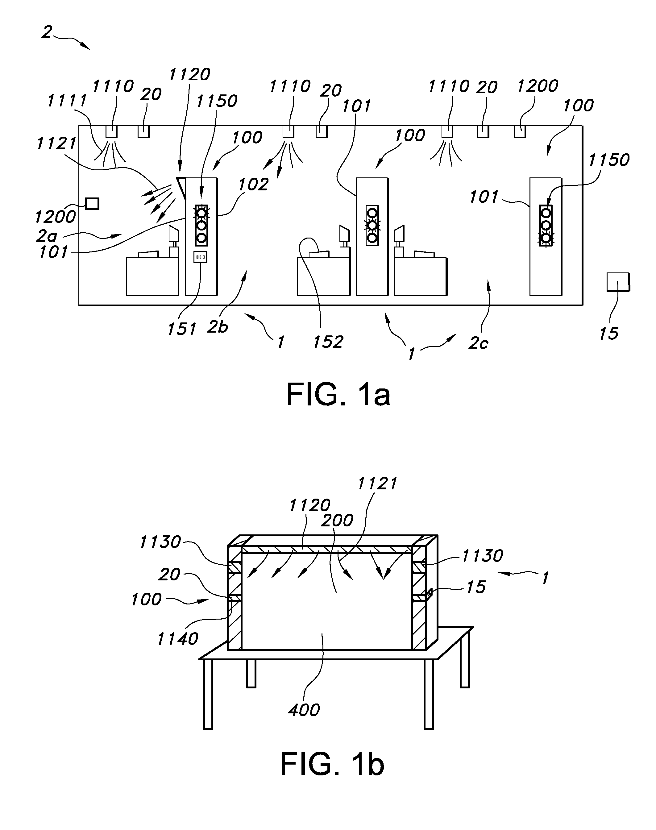
[0071]FIG. 1a schematically depicts a system 1 comprising the sound attenuating panel 100 as described herein, a control unit 15, and a sensor 20. The control unit 15 may be configured to control a device as function of a sensor signal from the sensor, wherein the device is selected from the group consisting of the sound attenuating panel 100 and another device, such as the further lighting in a space 2, wherein the panel(s) 100 are arranged. Optionally, the control unit may be configured to control one or more of the sound attenuating panels 100 and other device locally. Hence, in such way e.g. sound and or light can be controlled locally, such as indicated with subspaces 2a,2b,2c (which may e.g. cubicles). For instance, the sensor 200 comprises a sound sensor configured to measure sound in a space wherein the sound attenuating panel 100 is applied, configured to provide a corresponding sound sensor signal, wherein the sound attenuation properties of the sound attenuating panel 100...


PUM


Abstract

The invention provides a system (1) comprising a sound attenuating panel (100), a control unit (15), and a sound sensor (20), wherein the sound sensor (20) is configured to measure sound in a space wherein the sound attenuating panel (100) is applied and is configured to provide a corresponding sound sensor signal, wherein the control unit (15) is configured to control controllable devices as function of the sound sensor signal, wherein the controllable devices are a sound attenuating panel (100) having controllable properties and another device having controllable properties, said another device being selected from the group consisting of (i) a light source not embedded in the sound attenuating panel and (ii) a sound attenuating panel with a light source embedded therein.

Description

FIELD OF THE INVENTION[0001]The invention relates to a system comprising a sound attenuating panel, to a sound attenuating panel per se, as well as to a method to assist a human in performing an activity.BACKGROUND OF THE INVENTION[0002]Acoustic panels, such as for use in work spaces, are known in the art. An example of an acoustic panel can e.g. be found in WO 2013 / 085935. This document describes a sound absorbing luminaire providing lighting for an interior space environment and managing the acoustics within the environment. The luminaire includes a frame holding an acoustic film and a lighting element, forming a resonant cavity between them. The acoustic film is used for absorbing sound within the resonant cavity, and the lighting element provides light from a light source, such as LEDs, through the acoustic film. An optical film can be mounted in the frame between the acoustic film and the lighting element for providing a desired distribution of light.SUMMARY OF THE INVENTION[00...

Claims


Application Information

Patent Timeline
Patent Type & Authority Applications(United States)
IPC IPC(8): G10K11/162H05B37/02H05B33/08H04R29/00H05B44/00
CPCG10K11/162H05B33/0854H05B37/0236H04R29/00G01H3/10G10K11/16H05B45/10F21Y2115/10H05B47/12
Inventor KLABUNDE, KARINMASON, JONATHAN DAVIDMEERBEEK, BERENT WILLEMSARROUKH, BAHAA EDDINE
Owner SIGNIFY HLDG BV
Why Eureka
Try Eureka