
Degassing membrane for dialysis

a dialysis and membrane technology, applied in the field of degassing system, can solve the problems of air embolism, system and method cannot actively control the degassing process, and interfere with the proper functioning of the dialysis system

Active Publication Date: 2016-06-16
MOZARC MEDICAL US LLC
View PDF8 Cites 23 Cited by
  • Summary
  • Abstract
  • Description
  • Claims
  • Application Information

AI Technical Summary

Benefits of technology

The patent text describes a degassing system for dialysate during dialysis that uses a membrane to remove carbon dioxide. The membrane has a high permeability coefficient for carbon dioxide compared to nitrogen and / or oxygen, and a vacuum pump is used to create a low pressure vacuum on the other side of the membrane. The system can also have sensors to monitor the fluid level in the degassing vessel and adjust the flow rate accordingly. The method involves contacting a solution containing dissolved carbon dioxide with the membrane and controlling the gas pressure on the other side of the membrane to control the pressure of CO2 at the outlet of the degener. The technical effects of this invention include improved efficiency in removing carbon dioxide from dialysate, reduced risk of membrane fouling, and compatibility with different temperatures and pH levels.

Problems solved by technology

Removal of dissolved and undissolved gases from dialysate in a dialysis system can be important because dissolved gases can come out of solution in the dialysate circuit and cause gas bubbles, which can interfere with the proper functioning of the dialysis system.
Gas bubbles can interfere with the smooth pumping of the dialysate in the dialysate loop, interfere with sensors in the dialysate loop, and can present a dangerous condition for the patient if the gas bubbles cross the dialyzer membrane into the patient's blood stream, potentially causing an air embolism.
The known systems and methods cannot actively control a degassing process in order to selectively control a specific dissolved gas concentration within a desired range Instead, the systems described allow for general air removal from dialysate.

Method used

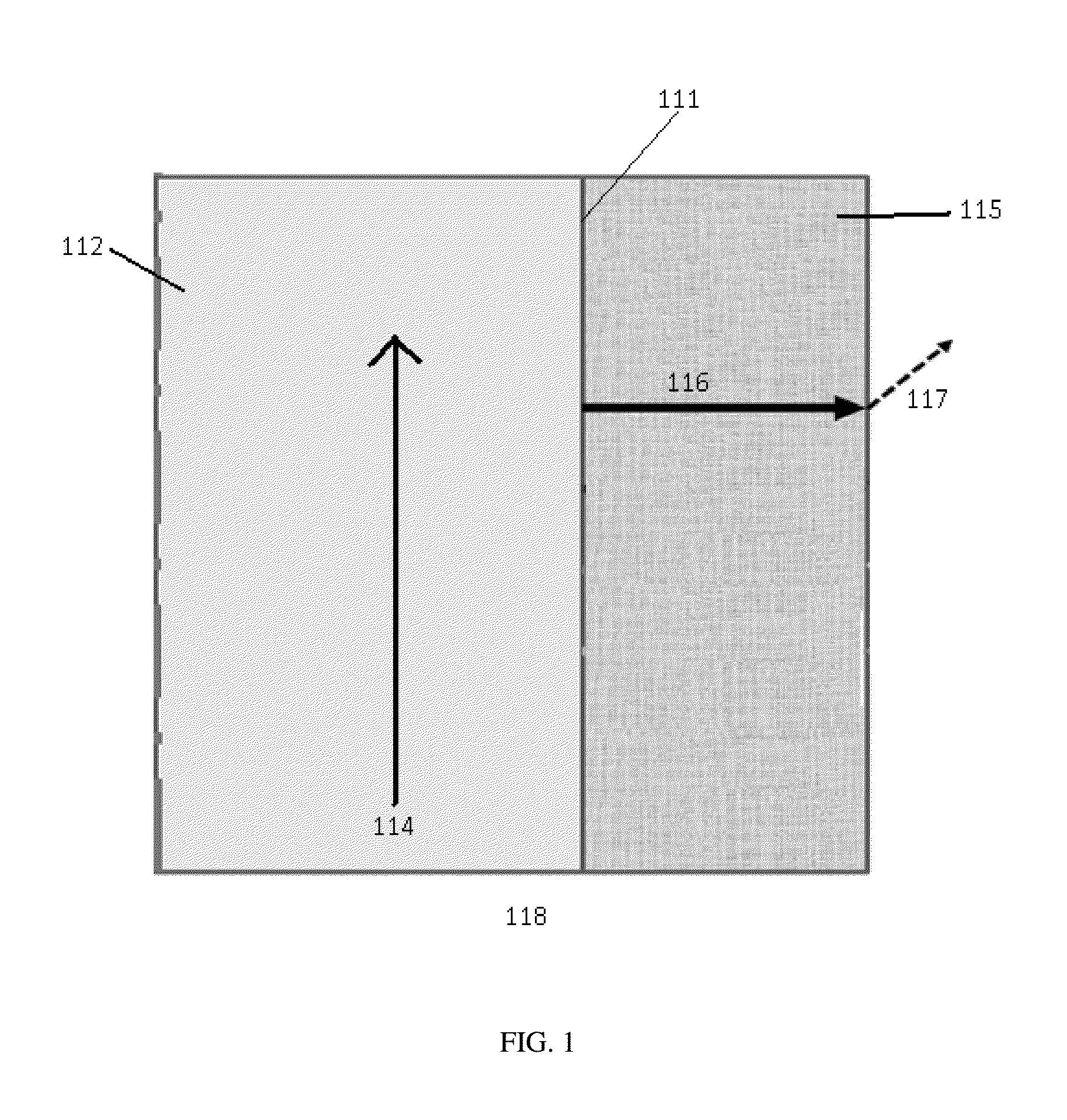
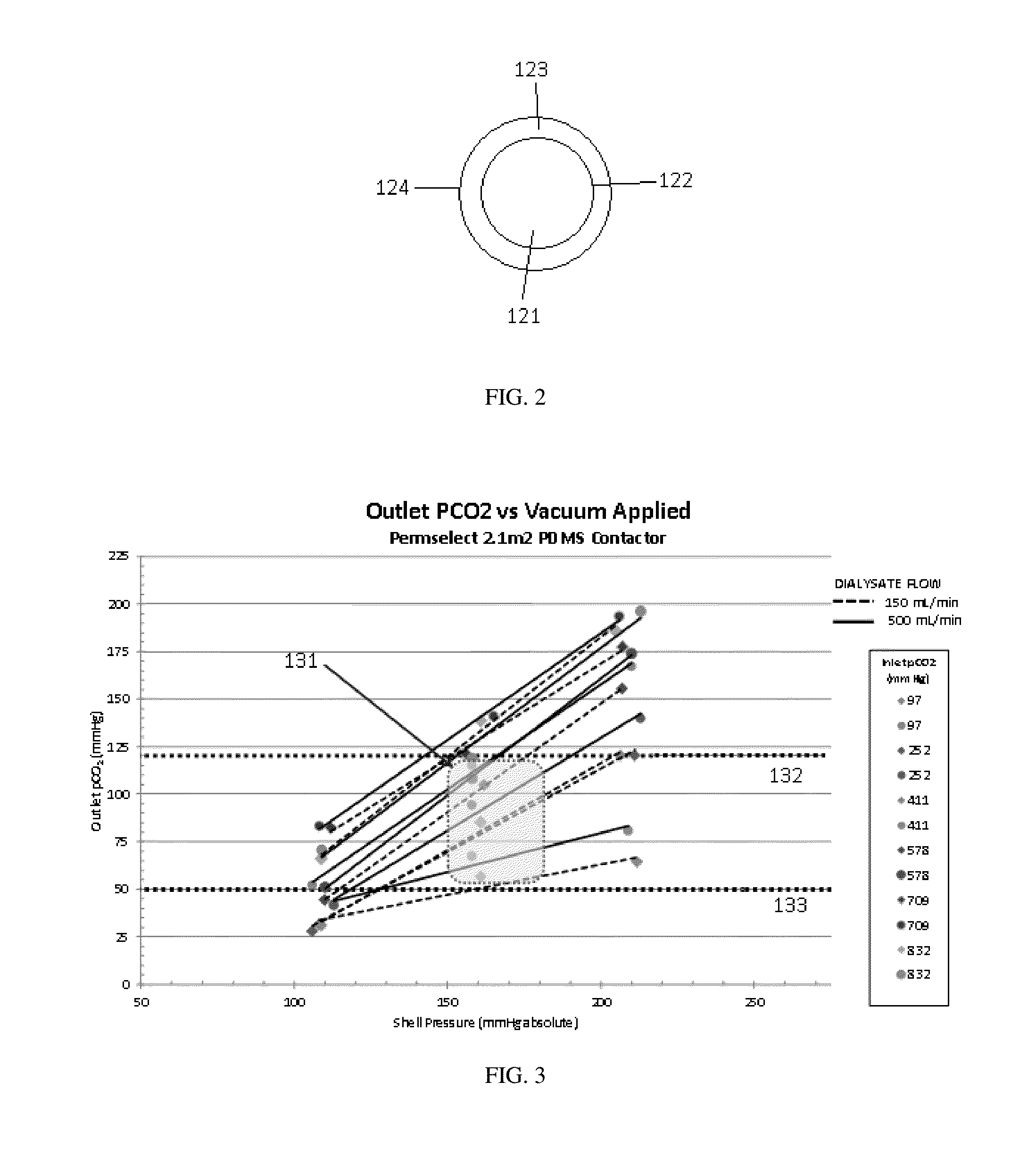
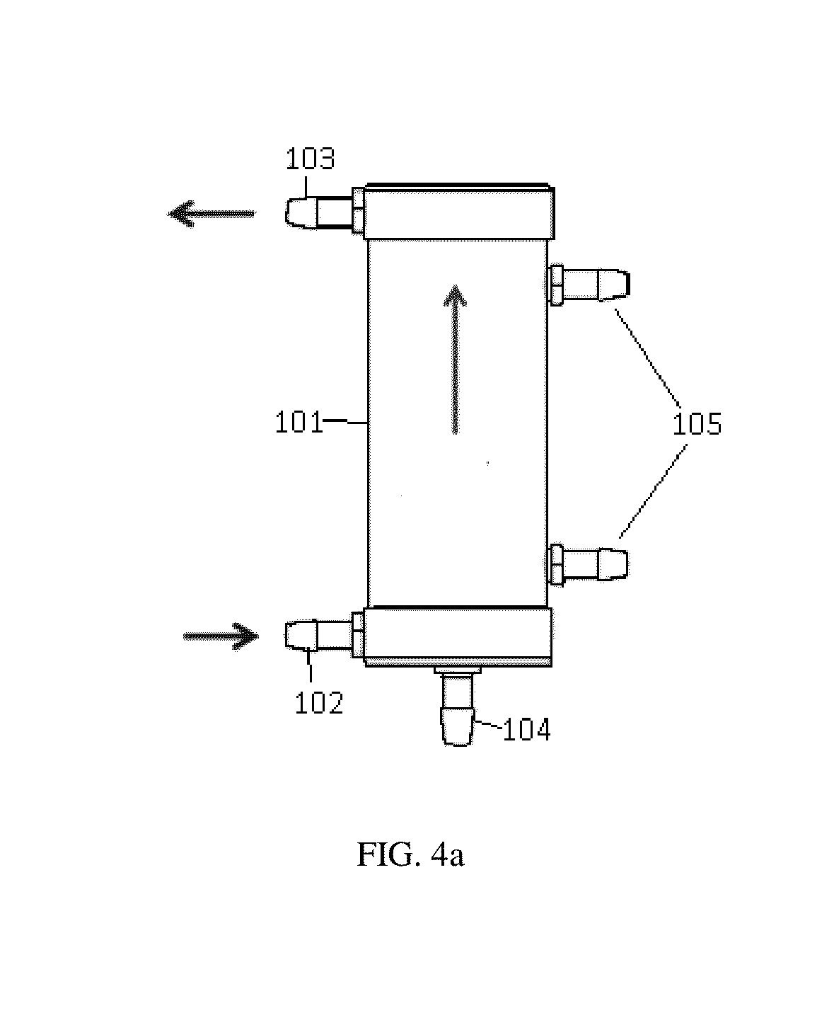

Image

  • Degassing membrane for dialysis
  • Degassing membrane for dialysis
  • Degassing membrane for dialysis

Examples


Embodiment Construction

[0037]Unless defined otherwise, all technical and scientific terms used herein generally have the same meaning as commonly understood by one of ordinary skill in the relevant art.

[0038]The articles “a” and “an” are used herein to refer to one or to more than one (i.e., to at least one) of the grammatical object of the article. By way of example, “an element” means one element or more than one element.

[0039]The term “cartridge” refers to any container designed to contain a powder, fluid, or gas made for ready connection to a device or mechanism. The container can have one or more compartments. Instead of compartments, the container can also be comprised of a system of two or more modules connected together to form the cartridge wherein the two or more modules once formed can be connected to a device or mechanism.

[0040]The term “comprising” includes, but is not limited to, whatever follows the word “comprising.” Thus, use of the term indicates that the listed elements are required or ...


PUM

PropertyMeasurementUnit
Temperatureaaaaaaaaaa
Fractionaaaaaaaaaa
Flow rateaaaaaaaaaa

Abstract

The degasser can have a degassing membrane that can be constructed from non-porous silica. The degassing membrane can be highly permeable to carbon dioxide but less permeable oxygen or nitrogen gases. Pressure in the dialysate and the degasser can be controlled in order to control the amount of carbon dioxide and other gases in dialysate leaving the degasser. The degassing membrane may be placed in a degassing module in a dialysate flow path to remove dissolved carbon dioxide from the dialysate.

Description

FIELD OF THE INVENTION[0001]The invention relates to a degassing system having a membrane for degassing fluids during dialysis and methods for using such a system and related methods.BACKGROUND[0002]Dialysis involves the movement of blood through a dialyzer having a semi-permeable membrane. The water supply used to initially prepare the dialysate or used during or after dialysis may contain a significant amount of dissolved gas such as nitrogen, oxygen, or carbon dioxide. Carbon dioxide may be formed as part of the breakdown of urea as spent dialysate flows through the sorbent cartridge. Removal of dissolved and undissolved gases from dialysate in a dialysis system can be important because dissolved gases can come out of solution in the dialysate circuit and cause gas bubbles, which can interfere with the proper functioning of the dialysis system. Gas bubbles can interfere with the smooth pumping of the dialysate in the dialysate loop, interfere with sensors in the dialysate loop, a...

Claims


Application Information

Patent Timeline
IPC IPC(8): A61M1/16B01D19/00
CPCA61M1/1658B01D19/0031B01D19/0073B01D19/0063B01D61/30B01D2325/20B01D71/701
Inventor MEYER, THOMAS E.
Owner MOZARC MEDICAL US LLC
Learn More